14 www.xilinx.com Getting Started with the VC707 Evaluation Kit
UG848 (v1.4.1) October 14, 2015
Chapter 1: Getting Started with the Virtex-7 FPGA VC707 Evaluation Kit
3. Turn off the VC707 board power (SW12) before installing the AMS 101 card on the
VC707 board XADC header J35.
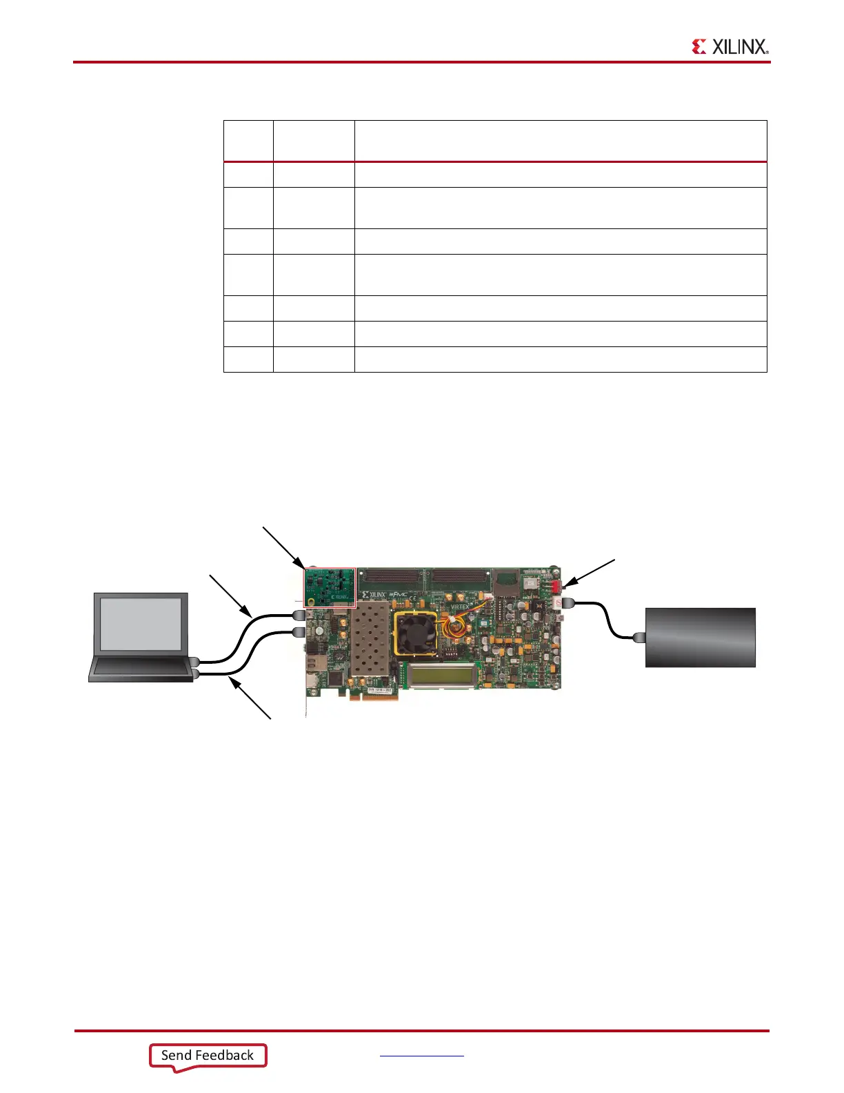
4. Plug the AMS 101 Card into the XADC header J35 on the VC707 board as shown in
Figure 1-11.
5. Connect the VC707 board to the host computer and power supply as shown in
Figure 1-11.
6. Turn board power on (SW12).
Examine Analog Mixed Signal Features
The AMS evaluator tool (Figure 1-13) is useful for examining analog signals in the time
and frequency domains, displaying linearity, viewing the XADC register settings, and
monitoring the internal FPGA temperature sensor and supply voltages. The AMS
evaluator tool also provides user-controllable decimation on the XADC output data to
enhance the signal-to-noise ratio (SNR) performance.
Table 1-2: AMS101 Evaluation Card Jumper and Component Notes
Callout
Reference
Designator
Notes
1 J2 External signal source input to V
P
positive analog input.
2 J3 Jumper on pins 1–2 selects DAC signal source.
Jumper on pins 2–3 selects external input source on J2.
3 20-pin connector to XADC header J35 on the VC707 board.
4 J5 Jumper on pins 1–2 selects DAC signal source.
Jumper on pins 2–3 selects external input source on J6.
5 J6 External signal source to V
N
negative analog input.
6 U3 16-bit DAC. Sets analog test voltage.
7 U2 Reference buffer for DAC.
X-Ref Target - Figure 1-11
Figure 1-11: BIST Board Connections
UG848_c1_19_040314
Power Supply
100VAC–240VAC Input
12 VDC 5.0A Output
To J18
Board Power
Switch SW12
USB cable
standard-A plug
to mini-B plug
To J17
(UART)
Host
Computer
USB cable
standard-A plug
to micro-B plug
To JTAG
AMS 101 Evaluation Card

 Loading...


