V5 series inverter
64
P3.42 Display parameters selection 2 Range: 0000~FFFF 0000
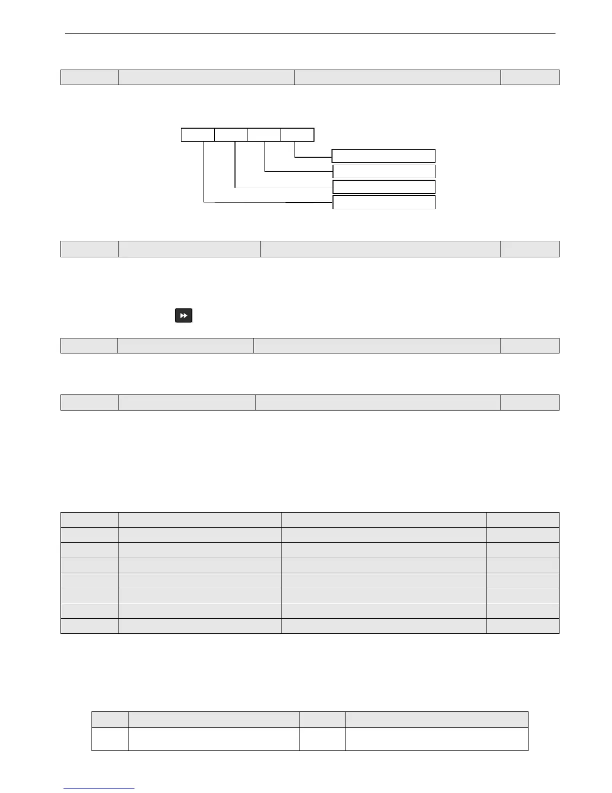
P3.42 uses the 4 bits of this parameter (hex value) to control the displaying of b-25~b-40. Please transform the parameter
to binary value when using. Each binary bit controls the displaying of one monitor parameter b. See Fig4-17.
P3.42 binary value:
Fig.4-17 Display parameters selection 2
P3.43 Display parameters selection 3 Range: 0000~4040 0001
Ten bit, lowest bit: used to set stop status
Thousand bit, hundred bit: used to set running status
Example: display current value in running status and display DC bus voltage value in stop mode, please set P3.43=0304.
You can also press the key to view other monitor parameters.
P3.44 Display coefficient without unit Range: 0.1~60.0 1.0
Display value of b-14 = Output frequency of inverter×P3.44 (proportion)
P3.45 JOG/REV switching Range: 0, 1 0
P3.45 is used to select the working mode of JOG/REV key on the operate panel:
0: JOG
1: REV
4-2-5. Function parameters of terminal (Group P4)
P4.00 Function selection of input terminal X1 Range: 0~37 1
P4.01 Function selection of input terminal X2 Range: 0~37 2
P4.02 Function selection of input terminal X3 Range: 0~37 3
P4.03 Function selection of input terminal X4 Range: 0~37 10
P4.04 Function selection of input terminal X5 Range: 0~37 17
P4.05 Function selection of input terminal X6 Range: 0~37 18
P4.06 Function selection of input terminal X7 Range: 0~37 0
P4.07 Function selection of input terminal X8 Range: 0~37 0
Multi-function input terminals X1~X8 support various functions. You can define the function of X1~X8 by setting
the value of P4.00~P4.07, refer to Table 4-1. Among these terminals, X7 corresponds to FWD and X8 corresponds to
REV.
Table 4-1 Multi-function selection
Setting Functions Setting Functions
0 Control terminals are idle 19 Frequency setting channel 1
 Loading...
