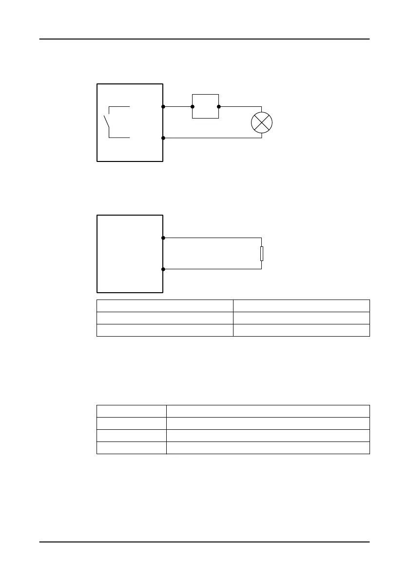
The digital outputs are potential free relay outputs. Connect a power supply
unit maximum 250 VAC, or 30 VDC, 5 A.
The digital outputs are configurable to be normally open or normally closed.
Analog output
8. Connect the analog output cables to the analog output terminal.
The analog output is active. The external circuit does not need an external
power source.
Signal Description
4 mA Minimum level
20 mA Maximum level
Power
9. Connect the power cables to the + 24 VDC terminal.
The power supply unit must fulfill isolation class II.
5.2.2 Set the switches
Set the switches.
Switch Correct setting
NODE ADDRESS, 0–9 All the node addresses in the system must be unique and not 0.
MASTER/SLAVE MASTER
TERM, ON/OFF ON
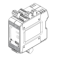
The groove is perpendicular to the arrow in the node address setting. This
image shows node address 1.
5 Electrical Installation
18 APP 412 Installation, Operation, and Maintenance manual
 Loading...