6 Operation
6.1 Startup and operation
For instructions about the system operation, see the System Installation and
Operation manual.
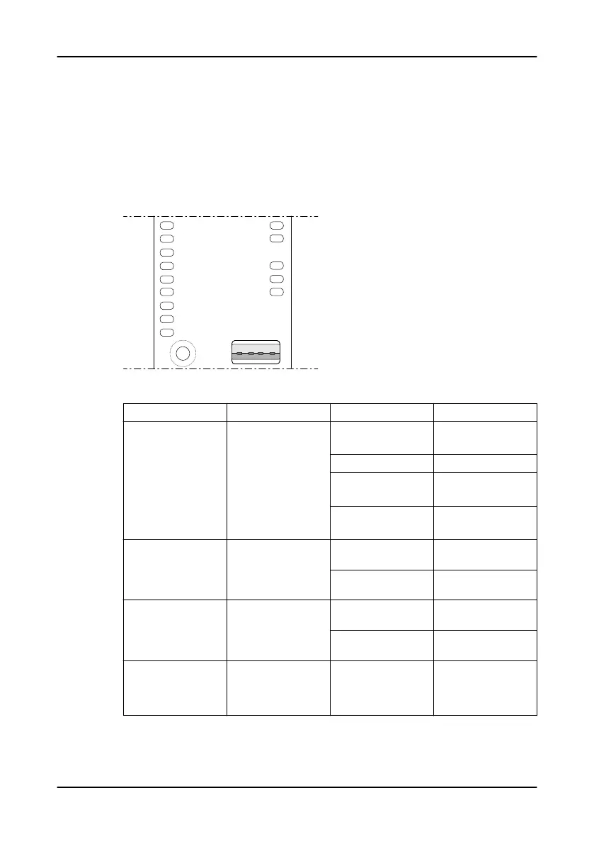
6.2 LED indicators
PWR
DI1
DI2
DI3
DI4
DO1
DO2
DO3
DO4
ALARM A
ALARM B
RUN
COMMS
RS485
USB
NODE
ADDRESS
1
2
3
4
5
6
7
8
9
0
WS010862A
Table 1: Normal operation
LED Description Color Indication
PWR Power Green The power is on.
21.6-26.4 V
– The power is off.
Orange 20.0-21.6 V
26.4-29.4 V
Red <20.0 V
>29.4 V
DI1 – DI4 Digital inputs Green The digital input is
active.
– The digital input does
not receive a signal.
DO1 – DO4 Digital outputs Green The digital output is
active.
– The digital output is
inactive.
ALARM A Alarm, Class A Flashing red The alarm is not
acknowledged. The
alarm condition is either
present or has ceased.
6 Operation
APP 412 Installation, Operation, and Maintenance manual 21
 Loading...