Modification for Packet Radio
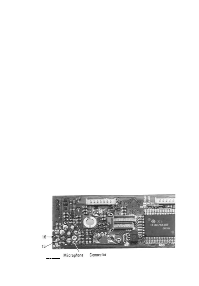
As supplied from the factory, pin 5 of the MIC jack is wired through solder bridge
jumper no. 16 on the Control Unit to allow tone burst activation via the BURST
button on the MH-14A8 microphone. For packet radio operation jumper 16 must be
removed, disabling BURST control, and jumper 15 installed to provide output of
the squelch BUSY line for packet radio tries.
(1) Remove the eight screws affixing the top and bottom covers, and the two
screws on each side. Remove the covers.
(2) Remove the ring nut and lockwasher around the MIC jack, and pull the
three knobs from the front panel.
(3) Without unclipping the plastic cover, grasp the front panel on the top and
bottom edges, and carefully slide it forward just enough to expose the
corner of the Control Unit pcb nearest the MIC jack.
(4) Using a fine-tipped soldering iron and solder wick or a solder sucker,
remove the solder bridge from BURST jumper pad 16, and then add
solder to bridge BUSY pad 15.
(5) Press the front panel assembly gently back into place (so that the holes in
each side are aligned with those in the chassis). Replace the ring nut and
washer over the MIC jack, and the knobs. Replace the top and bottom
covers and their eight screws, and the four screws in the sides.
17
 Loading...