3
G-800DXA / -1000DXA / -2800DXA User Manual
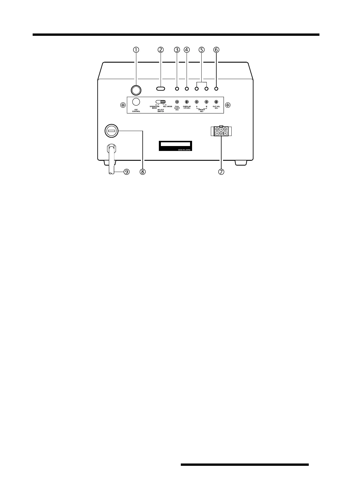
Controller Rear Panel
À
EXT CONTROL
Connector
This 6 pin mini-DIN connector is used for connection
to the optional
GS-232B
Computer Control Unit.
Á
SELECT SWITCH
Set this switch to the “
ADJ. MODE
” position while
calibrating the internal adjustments of the controller.
During normal operation, however, set this switch to
the “
OPERATION MODE
” position.
Â
FULL SCALE ADJ
Potentiometer
This control calibrates the maximum rotation angle
(range) of the azimuth indicating needle to match the
maximum angle of the rotator.
Ã
OVERLAP LED ADJ
Potentiometer
This control calibrates the
OVERLAP
Indicator to
match the azimuth indicating needle.
Ä
PRESET ADJ
(
A
&
B
) Potentiometers
These controls calibrate the angle of the
PRESET
control on the front panel to match the azimuth indi-
cating needle. Pot.
A
should be adjusted only near the
180
ー
position, and Pot.
B
only near the 270° (450°)
position.
Å
OUT VOL ADJ
Potentiometer
This control presets the voltage range at pin 4 of the 6
pin mini-DIN
EXT CONTROL
Connector, for cali-
bration of the A-to-D converter on the (optional)
GS-
232B
Computer Control Unit.
Æ
Rotator Control Cable Jack
The control cable from the rotator connects to this 6
pin jack.
Ç
FUSE Holder
This holder requires a 2 A fuse for 117 V AC, and a
1 A fuse for 220 V AC. If the fuse is blown, replace
only with a fuse of the same rating.
È
AC Cable
Connect this cable to the AC mains supply or wall
outlet. The AC line voltage must match that on the
label.
YAESU MUSEN CO., LTD.
 Loading...