5-35
WIRING DIAGRAMS
Some representative wiring diagram samples for Yamaha genuine remote controls and instruments
are shown here. These diagrams will cover most common configurations.
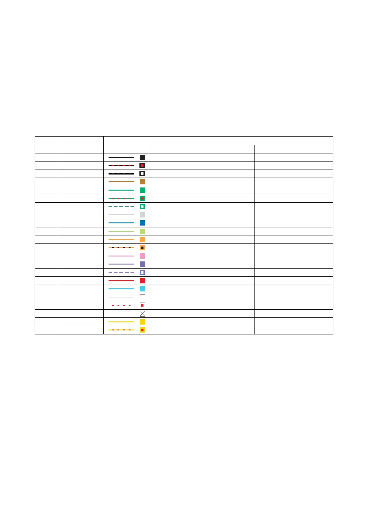
WIRE COLOR CODE
The wiring color code and the main usage for the electric wires are shown as below.
The wire color and its main usage are difference between Yamaha standard and ABYC standard.
* For the wires which use tracer stripes, the main color is followed by a slash then the tracer color.
For example:
R/G = Red wire with a green tracer stripe
Pu/W = Purple wire with a white tracer stripe
Color
code
Wire color Color sample
Main usage
Yamaha standard ABYC standard
B Black Ground, Battery (–) Ground
B/R Black/Red Remote-oil tank
B/W Black/White Ignition coil primary
Br Brown Neutral switch Generator
G Green Lighting coil 1 (tach signal 1) Ground
G/R Green/Red Oil warning
G/W Green/White Lighting coil 2 (tach signal 2)
Gy Gray Warning signal Tacho signal
L Blue Instrument light, Remote choke Instrument light
Lg Light green Trim down
Or Orange Trim sender
Or/B Orange/Black
P Pink Overheat warning, Trim signal Fuel sender
Pu Purple ECM Switched 12 volts supply
Pu/W Purple/White
R Red Permanent 12 volts supply, Battery (+) Battery (+)
Sb Sky blue Trim up Oil pressure
W White Engine stop switch
W/R White/Red Pulser coil
X N/A Not used
Y Yellow Switched 12 volts supply
Y/R Yellow/Red Diagnosis Starting motor
 Loading...