14
RX-V459/HTR-5940/DSP-AX459
HTR-5935
RX-V459/HTR-5940/DSP-AX459
HTR-5935
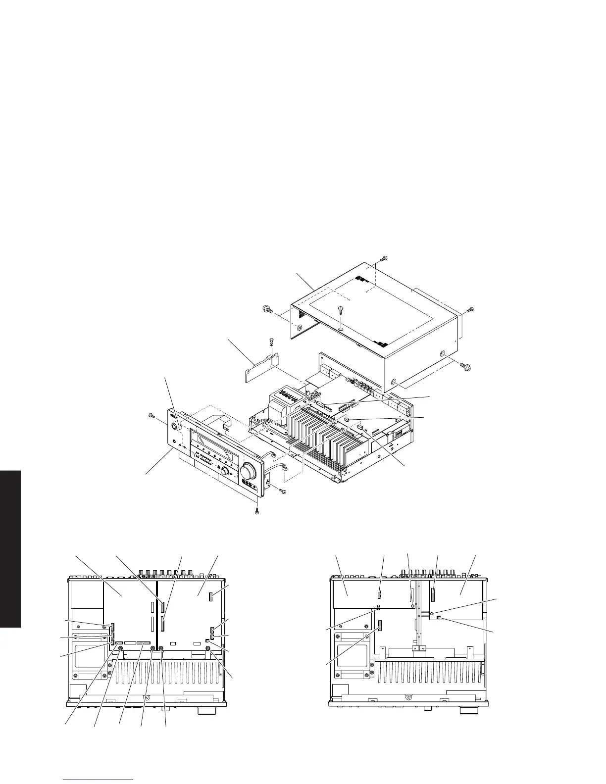
■ DISASSEMBLY PROCEDURES / 分解手順
(Remove parts in the order as numbered.)
Disconnect the power cable from the AC outlet.
1. Removal of Top Cover
a. Remove 4 screws (1), 5 screws (2) and 1 screw (3).
(Fig. 1)
b. Slide the Top Cover rearward to remove it. (Fig. 1)
2. Removal of Front Panel Unit
a. Remove 6 screws (4). (Fig. 1)
b. Remove a push rivet (5). (Fig. 1)
c. Remove the Barrier/FFC. (Fig. 1)
d. Remove CB5, CB203, CB205 and CB310. (Fig. 1)
e. Remove the Front Panel Unit. (Fig. 1)
(番号順に部品を取り外してください。)
AC電源コンセントから、電源コードを抜いてください。
1. トップカバーの外し方
a.
1
のネジ4本、
2
のネジ5本、
3
のネジ1本を外します。
(Fig.1)
b. トップカバーを後方へスライドさせ、取り外します。(Fig.1)
2. フロントパネルユニットの外し方
a.
4
のネジ6本を外します。(Fig.1)
b.
5
プッシュリベット1本を外します。(Fig.1)
c. バリアー/FFCを取り外します。(Fig.1)
d. CB5、CB203、CB205、CB310を外します。(Fig.1)
e. フロントパネルユニットを取り外します。(Fig.1)
Fig. 1
1
1
2
3
2
CB205
CB203
CB5
CB310
4
4
4
5
Top Cover
トップカバー
Front Panel Unit
フロントパネルユニット
Barrier / FFC
バリアーFFC
Fig. 2
CB202 CB200
CB204
CB206
CB207
CB201
CB2CB3
CB9
CB4
CB57
FUNCTION (1) P.C.B.DSP P.C.B.
6
688
Fig. 3
CB252CB103
CB251
CB105
(
U, C models
)
CB104
FUNCTION (2) P.C.B. OPERATION (2) P.C.B.
0
B
 Loading...