15
RX-V459/HTR-5940/DSP-AX459
HTR-5935
3. Removal of FUNCTION (1) P.C.B.
a. Remove 2 screws (6). (Fig. 2)
b. Remove 7 screws (7). (Fig. 4)
c. Remove CB200-202, CB204, CB206 and CB207.
(Fig. 2)
d. Remove the FUNCTION (1) P.C.B.. (Fig. 2)
4. Removal of DSP P.C.B.
a. Remove 2 screws (8). (Fig. 2)
b. Remove 4 screws (U, C models) / 3 screws (R, T, K,
A, G, E, L models) (9). (Fig. 4)
c. Remove CB2-4, CB9 and CB57. (Fig. 2)
d. Remove the DSP P.C.B.. (Fig. 2)
5. Removal of OPERATION (2) P.C.B.
a. Remove 1 push rivet (0). (Fig. 3)
b. Remove 6 screws (A). (Fig. 4)
c. Remove CB251 and CB252. (Fig. 3)
b. Remove the OPERATION (2) P.C.B.. (Fig. 3)
6. Removal of FUNCTION (2) P.C.B.
a. Remove 1 push rivet (B). (Fig. 3)
b. Remove 5 screws (C). (Fig. 4)
c. Remove the FUNCTION (2) P.C.B.. (Fig. 3)
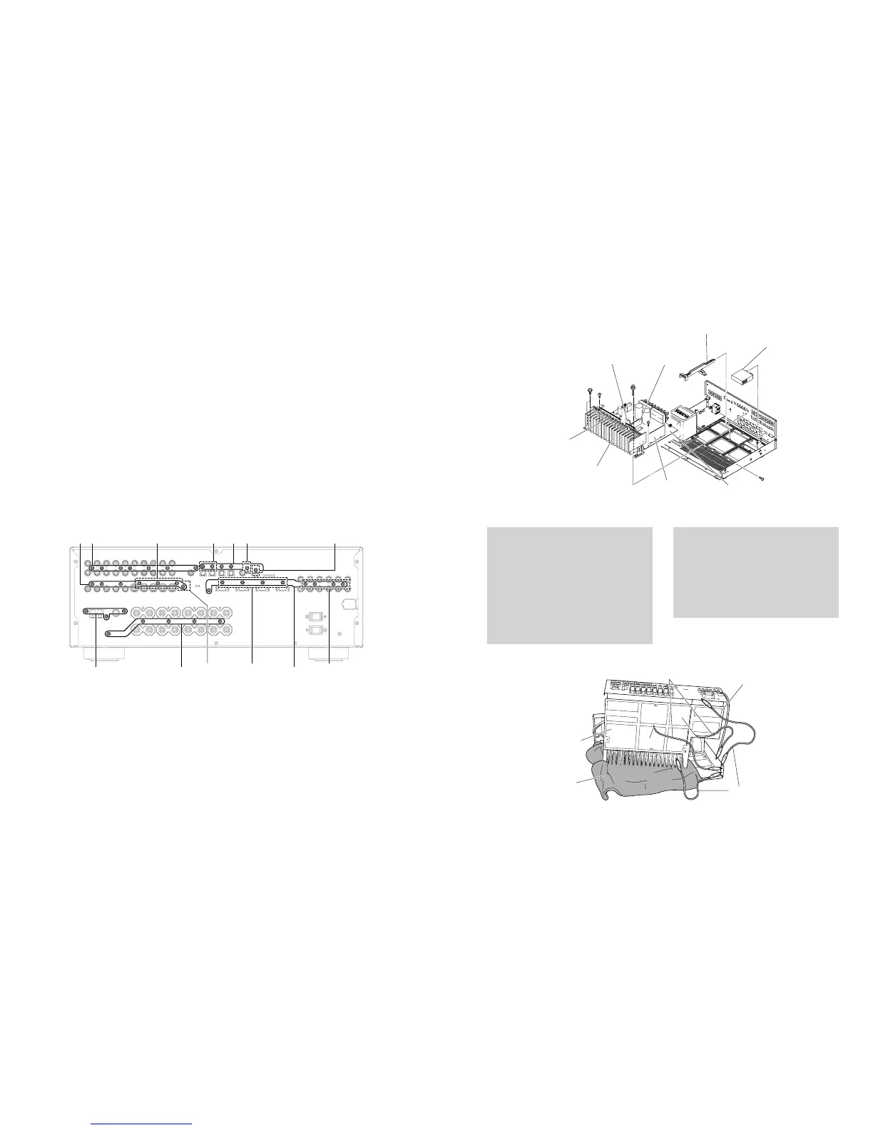
Fig. 4
P.C.B.チェックする場合
・ 布を敷きます。その上にP.C.B.をヒートシンクと一緒に立
ててチェックします。(Fig.6)
・ 外したケーブル(コネクター)をすべて接続してください。
・ フラットケーブルを接続する際、極性に注意してくださ
い。
・ シャーシから外したP.C.B.はアースが浮いて動作しません
ので、MAIN(1)P.C.B.(G1001)、OPERATION(4)
P.C.B.(G3001)のアースをリード線等でシャーシまたは
GNDに接続してください。(Fig.6)
When checking the P.C.B.:
• Put a Cloth over the equipment. Put the P.C.B.s
together with the Heat Sink upright on the Cloth and
check them. (Fig. 6)
• Reconnect all cables (connectors) that have been
disconnected.
• When connecting the flat cable, use care for the
polarity.
• The P.C.B. removed from the chassis does not work
because its grounding is loose. Be sure to connect
the ground of Rear Panel, MAIN (1) P.C.B. (G1001)
and OPERATION (4) P.C.B. (G3001) to the chassis
with a ground lead or the like. (Fig. 6)
7
D I C
A 9
J modelHTR-5935 model U, C, R, T, K, A, G, E, L models
U, C modelsJ model U, C, R, T, K, A, G, E, L modelsRX-V459/HTR-5940/DSP-AX459 models
H
F
E
E
G
MAIN (1) P.C.B.
MAIN (2) P.C.B.
YST P.C.B. (HTR-5935)
MAIN (4) P.C.B.
MAIN (5) P.C.B.
Tuner
チューナー
Heat Sink
ヒートシンク
Artbase / P.C.B.
アートベース/P.C.B.
7. TUNERの外し方
a.
D
のネジ3本を外します。(Fig.4)
b. TUNERを取り外します。(Fig.5)
8. MAIN(1)、(2)、(4)、(5)P.C.B.の外し方
a. アートベース/PCBを取り外します。(Fig.5)
b.
E
のネジ2本、
F
のネジ1本、
G
のネジ2本、
H
のネジ1本を
外します。(Fig.5)
c.
I
のネジ5本を外します。(Fig.4)
d. CB103、CB104を外します。(Fig.3)
e. MAIN(1)、(2)、(4)、(5)P.C.B.をヒートシンクと一緒に取
り外します。(Fig.5)
3. FUNCTION(1)P.C.B.の外し方
a.
6
のネジ2本を外します。(Fig.2)
b.
7
のネジ7本を外します。(Fig.4)
c. CB200〜202、CB204、CB206、CB207を外します。
(Fig.2)
d. FUNCTION(1)P.C.B.を取り外します。(Fig.2)
4. DSPP.C.B.の外し方
a.
8
のネジ2本を外します。(Fig.2)
b.
9
のネジ5本を外します。(Fig.4)
c. CB2〜4、CB9、CB57を外します。(Fig.2)
d. DSPP.C.B.を取り外します。(Fig.2)
5. OPERATION(2)P.C.B.の外し方
a.
0
のプッシュリベット1本を外します。(Fig.3)
b.
A
のネジ6本を外します。(Fig.4)
c. CB251、CB252を外します。(Fig.3)
d. OPERATION(2)P.C.B.を取り外します。(Fig.3)
6. FUNCTION(2)P.C.B.の外し方
a.
B
のプッシュリベット1本を外します。(Fig.3)
b.
C
のネジ5本を外します。(Fig.4)
c. FUNCTION(2)P.C.B.を取り外します。(Fig.3)
7. Removal of TUNER
a. Remove 3 screws (D). (Fig. 4)
b. Remove the Tuner. (Fig. 5)
8. Removal of MAIN (1), (2), (4), (5) and YST (HTR-5835
model) P.C.B.s
a. Remove the Artbase/P.C.B.. (Fig. 5)
b. Remove 2 screws (E), 1 screw (F), 2 screws (G)
and 1 screw (H). (Fig. 5)
c. Remove 5 screws (I). (Fig. 4)
d. Remove CB103, CB104 and CB105 (U, C models). (Fig. 3)
e. Remove MAIN (1), (2), (4), (5) and YST (HTR-5835
model) P.C.B.s together with the Heat Sink. (Fig. 5)
Fig. 5
Cloth
布
Ground lead
アース線
OPERATION (4) P.C.B.
Ground lead
アース線
G1001
G3001
MAIN (1) P.C.B.
Fig. 6
 Loading...