CIRCUIT DIAGRAM
MIXING CONSOLE
MG16/6FX
CONTENTS
BLOCK DIAGRAM
.................... 3
OVERALL CIRCUIT DIAGRAM
Note: See parts list for details of circuit board component parts.
MAIN .......................................................................... 4-10
JACK 1/2 ................................................................. 11, 12
JACK 2/2 ......................................................................... 8
DSP ................................................................................ 13
PS................................................................................... 14
PHANTOM
(シート間コネクタの読み方について)
(ページNo.は信号の行先ページを示します。)
(回路図表記上の注意)
Notation for Circuit Diagrams
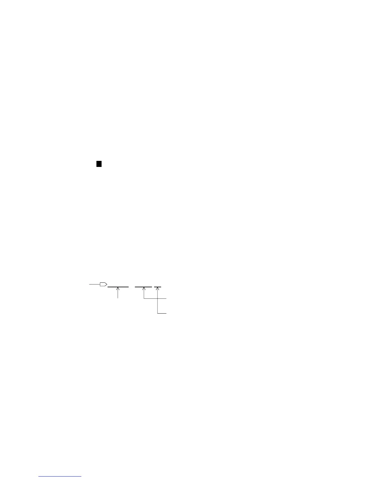
1. How to identify inter-sheet connectors
The page number indicates the destination page.
対応するシート間のコネクタのあるロケーションを示します。
(アルファベットが水平方向、数字が垂直方向)
This indicates the location of the counter inter-sheet connector.
(The alphabet indicates horizontal direction and the number
indicates vertical direction)
to page 6: P9
Signal name
(信号名)
&LEVELDIAGRAM
(ブロックダイアグラム&レベルダイアグラム)
(総回路図)
(目次)
注:シートの部品詳細はパーツリストをご参照ください。

 Loading...