QL5/QL1
120
6. Lamp Voltage Measurement
QL5: Measure the voltage between pins No.3 and No.4 at 2
places on the rear panel.
QL1: Measure the voltage between pins No.3 and No.4 at 1
place on the rear panel.
Measure the voltage when the LAMP DIMMER is at MAX and
MIN positions.
7. Fan Operation Check
After turning on the power switch, check that no fan operation
error is shown on the display.
8. MY SLOT Power Check
Parameters: For the “MY SLOT card for testing”, use the one
with the extended cable for the power voltage
check connected to each land terminal of CN102
of MY16-EX.
INSPECTIONS
Insert the MY SLOT card for testing into all the MY SLOT
openings of the main unit and measure each power voltage with
the tip of the cable.
SETTINGS FOR SHIPMENT
1. Initialization
While pressing the master section A and B
[SEL]
switches
at the same time, turn on the power for forced initialization.
After that, "Flash Memory Initializing Finished" will appear as
confi rmation. Then press
[CLOSE]
to end the procedure.
2. Settings of operation elements
Set each operation element as follows.
PHONES LEVEL: MIN
Judgment criteria 1:
Confi rm that the EFFECT sound is output.
Judgment criteria 2:
Confi rm that the output is free from noise.
In the same manner, recall scenes 6 through 36 and check by
listening.
The scene numbers and EFFECT types are as follows.
e DANTE input/output check
Parameters:
Set the OUTPUT button of OSCILLATOR on the
monitor screen to ON in advance.
At the end of Cubage reproduction in the EFFECT
sound output check, Scene 38 for DANTE input/
output check will be recalled.
Listen to the sound of the oscillator for 15 seconds to
check that no noise is included.
For the details, refer to “DANTE sound output
check” on page 170.
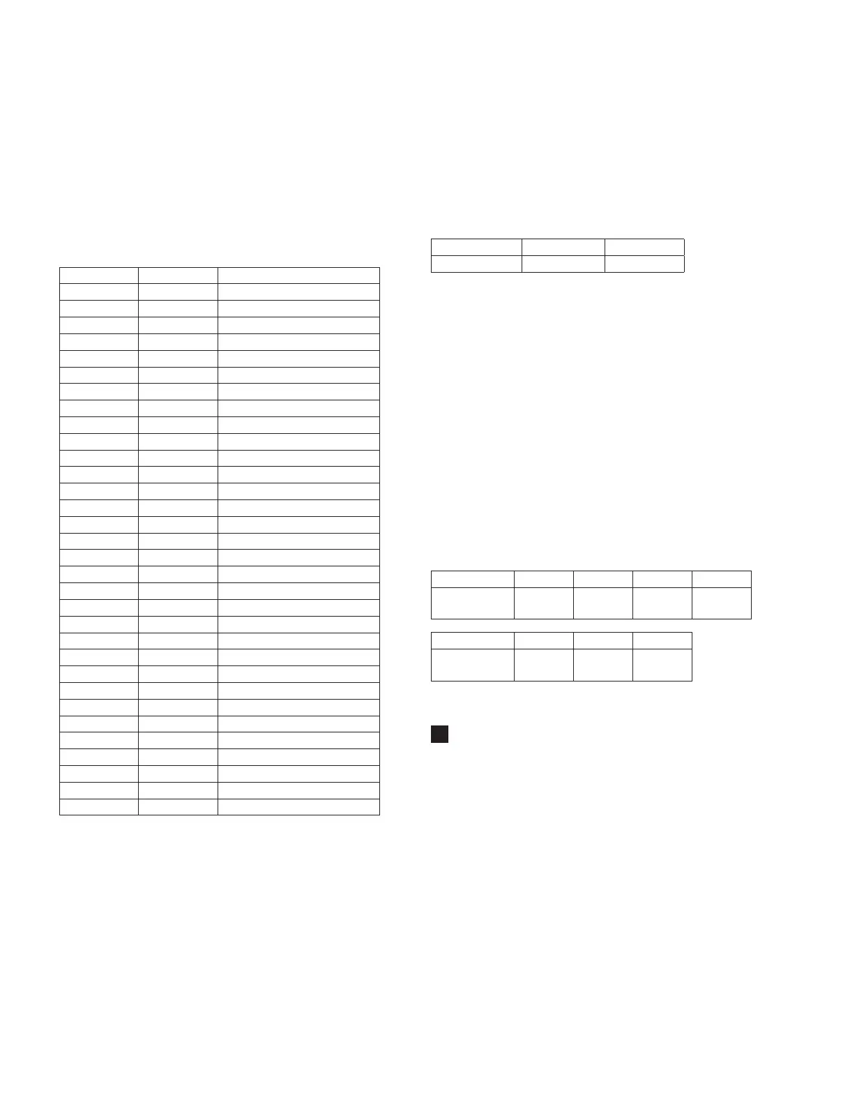
Terminal Name
+3.3D +5D +15A –15A
Power Voltage
Permissible Range
3.3±0.3 V 5.0±0.5 V 15.0±0.8 V –15.0±0.8 V
Terminal Name
+5A –5A +20A
Power Voltage
Permissible Range
5.0±0.3 V –5.0±0.3 V 20.0±1.0 V
Scene No. Rack No. EFFECT TYPE
5 1 Reverb
6 1 Symphonic
7 1 HQ Pitch
8 1 Dynamic Filter
9 2 Reverb
10 2 Symphonic
11 2 Dual Pitch
12 2 Dynamic Filter
13 3 Reverb
14 3 Symphonic
15 3 HQ Pitch
16 3 Dynamic Filter
17 4 Reverb
18 4 Symphonic
19 4 Dual Pitch
20 4 Dynamic Filter
21 5 Reverb
22 5 Symphonic
23 5 HQ Pitch
24 5 Dynamic Filter
25 6 Reverb
26 6 Symphonic
27 6 Dual Pitch
28 6 Dynamic Filter
29 7 Reverb
30 7 Symphonic
31 7 HQ Pitch
32 7 Dynamic Filter
33 8 Reverb
34 8 Symphonic
35 8 Dual Pitch
36 8 Dynamic Filter
MAX MIN
Permissible Range
12.0 V±1.0 V 0 V±0.5 V
 Loading...


