17
RX-V681/RX-A760
RX-V681/RX-A760
■ DISASSEMBLY PROCEDURES
RX-V681
(Remove parts in the order as numbered.)
Disconnect the power cable from the AC outlet.
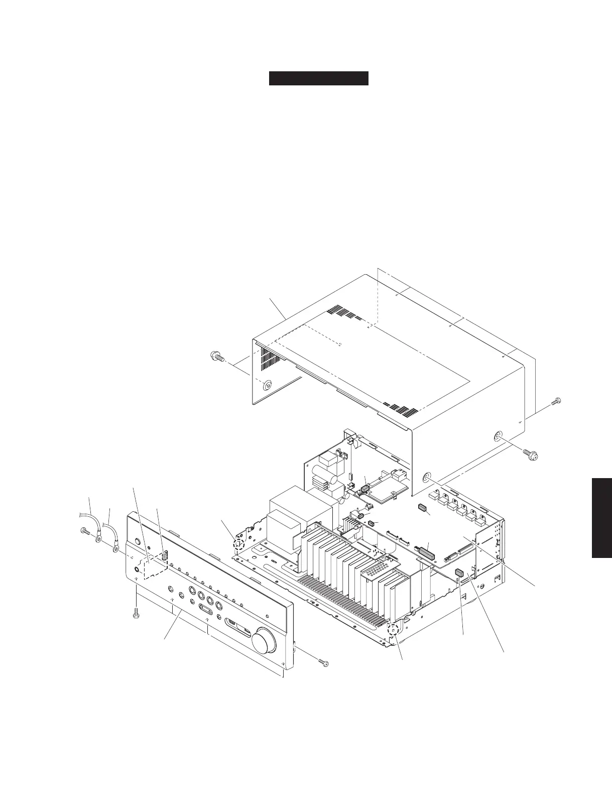
1. Removal of Top Cover
a. Remove 4 screws (
1
) and 5 screws (
2
). (Fig. 1)
b. Lift the rear side of the top cover to remove it. (Fig. 1)
2. Removal of Front Panel Unit
a. Remove 6 screws (
3
), and remove W301 and W307. (Fig. 1)
b. Remove CB1, CB6, CB82, CB308, CB343, CB941 and CB951. (Fig. 1)
c. Release 2 hooks, and remove the front panel unit. (Fig. 1)
Fig. 1
CB343
DIGITAL (1) P. C.B.
OPERATION (2) P. C.B.
Hook
Front panel unit
③
③
CB308
W307
W301
OPERATION (7) P. C.B.
③
Hook
①
②
CB82
CB1
CB6
CB941
CB951
Top cover
①
 Loading...