349215-JIM-B-1008
44 Johnson Controls Unitary Products
PHASING
Johnson Controls MODEL J**DJ, units are properly
phased at the factory. Check for proper compressor
rotation. If the blower or compressors rotate in the
wrong direction at start-up, the electrical connection to
the unit is misphased. Change the incoming line con-
nection phasing to obtain proper rotation. (Scroll com-
pressors operate in only one direction. If the scroll is
drawing low amperage, has similar suction and dis-
charge pressures, or producing a high noise level, the
scroll is misphased).
CHECKING SUPPLY AIR CFM
The RPM of the supply air blower will depend on the
required CFM, the unit accessories or options and the
static resistances of both the supply and the return air
duct systems. With this information, the RPM for the
supply air blower and the motor pulley adjustment
(turns open) can be determined from the Blower Per-
formance Data Tables.
High speed drive accessories (containing a smaller
blower pulley and a shorter belt) are available for appli-
cations requiring the supply air blower to produce
higher CFM's and/or higher static pressures. Use
Model 1LD0460 for 15 ton units, Model 1LD0417 for
17.5 and 20 ton units, and Model 1LD0435 for 25 ton
units. Refer to the Blower Motor and Drive Data
Table 21.
Note the following:
1. The supply air CFM must be within the limitations
shown in the Unit Application Data Table 1.
2. Pulleys can be adjusted in half turn increments.
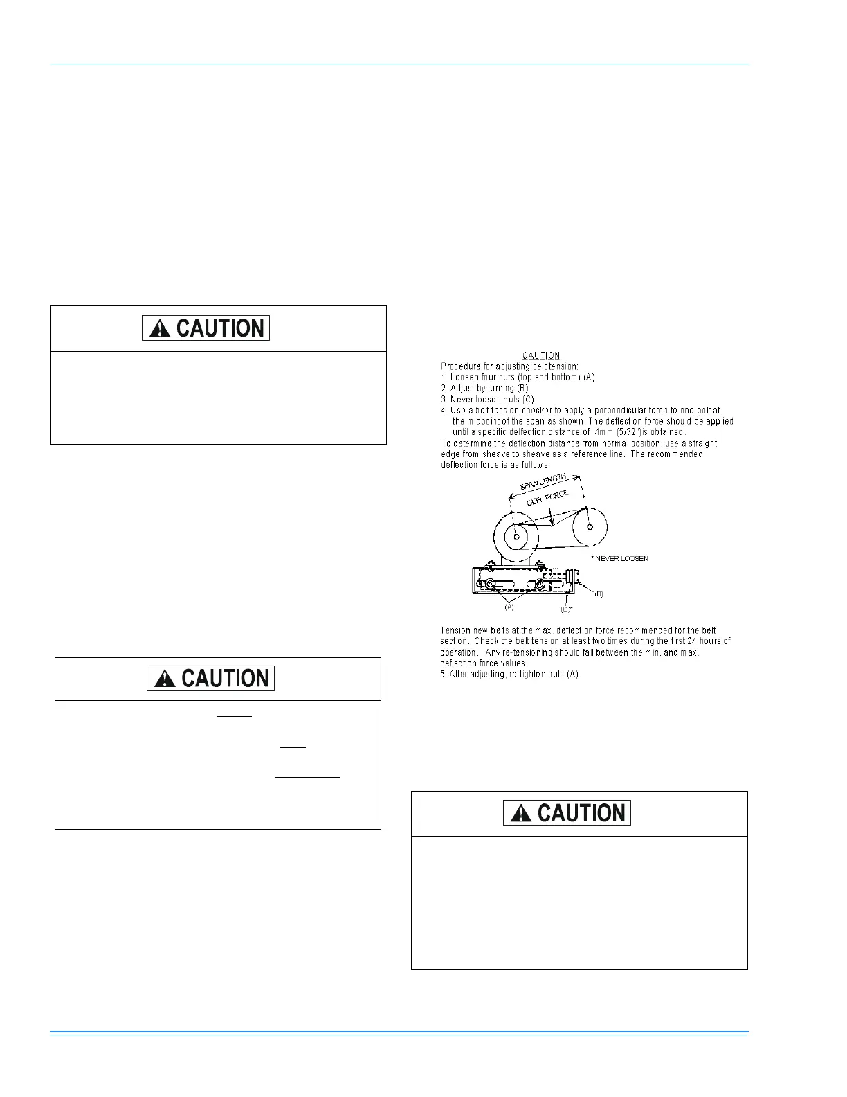
3. The tension on the belt should be adjusted as
shown in the Belt Adjustment Figure 21.
4. Tighten blower pulley and motor sheave set screws
after any adjustments. Re-check set screws after
10-12 hrs. run time is recommended.
AIR BALANCE
Scroll compressors require proper rotation to
operate correctly. Units are properly phased at
the factory. Do not change the internal wiring to
make the blower, condenser fans, or compres-
sor rotate correctly.
Belt drive blower systems MUST be adjusted to the
specific static and CFM requirements for the
application. The belt drive blowers are NOT
set at the
factory for any specific static or CFM. Adjustments of
the blower speed an belt tension are REQUIRED
.
Tighten blower pulley and motor sheave set screws
after these adjustments. Re-checking set screws
after 10-12 hrs. run time is recommended.
FIGURE 21 - BELT ADJUSTMENT
On VAV units be certain that the VFD drive is
set to maximum output, exhaust dampers are
closed and individual space damper boxes are
full open.
VFD units with bypass must not be in bypass
mode (‘LINE’ position) unless all individual
space dampers are full open.

 Loading...