349215-JIM-B-1008
66 Johnson Controls Unitary Products
NOTE: While in either Setup mode, if no buttons are
pushed for 60 seconds, the display will revert
to its normal display, exiting the Option Setup
mode. When saving, the control board only
saves the parameters for the currently dis-
played mode (Option Byte or Heat Delay).
OPTIONAL VAV CONTROL BOARD FLASH CODES
Flash codes are also utilized by the VAV add-on board to aid
in troubleshooting optional VAV applications. Flash codes are
displayed by a red LED located near the center of the board
using a short on/off cycle (approximately 200-ms on and 200-
ms off).
To verify that the board is functioning correctly, the LED will
display a repetitive 1 second on, 1 second off "heartbeat". Do
not confuse this "heartbeat" with the error flash codes shown
in the table below. To prevent confusion, a 1-flash, flash code
is not used.
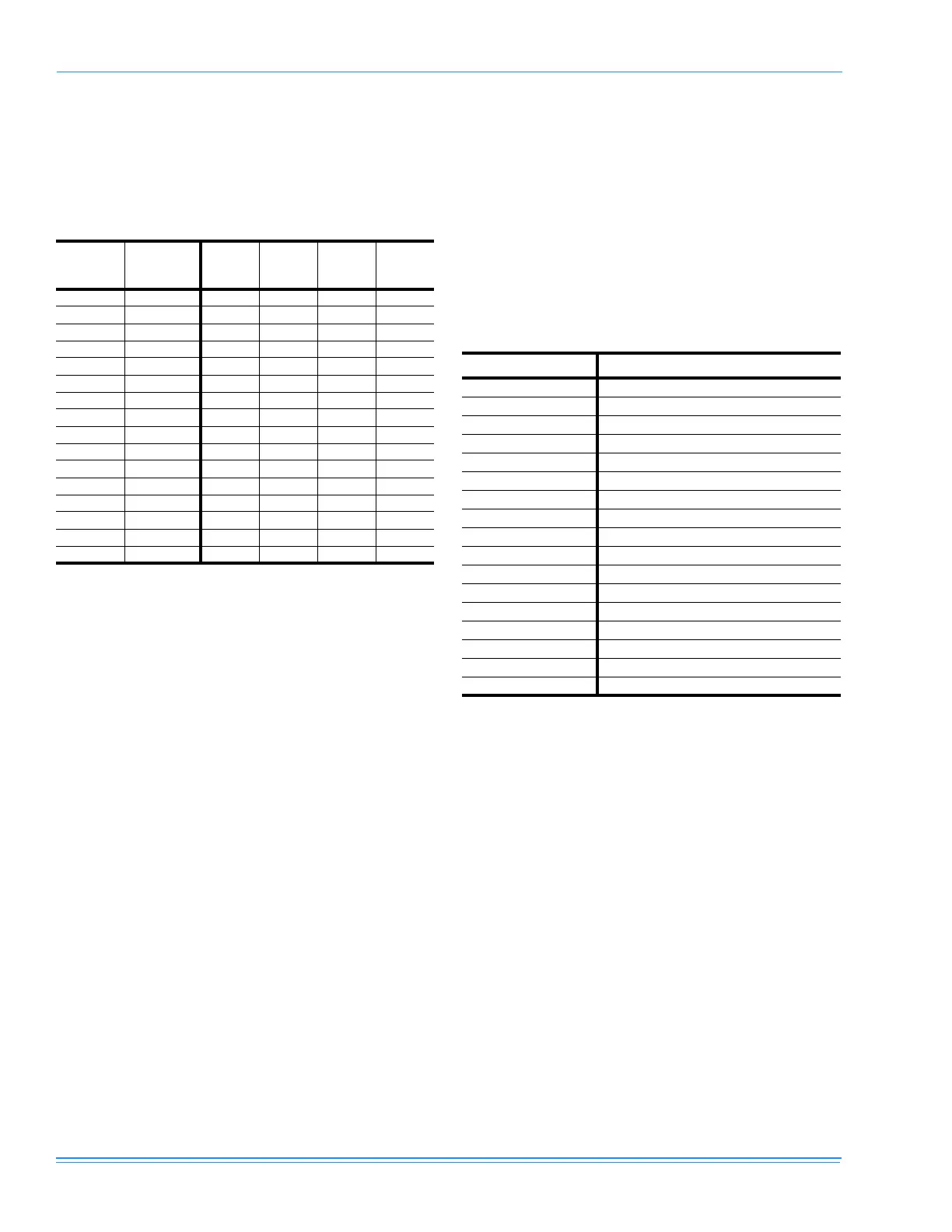
TABLE 28: HEAT DELAY
Heat
Fan On
Delay
Heat
Fan Off
Delay
Red
LED 8
Red
LED 4
Red
LED 2
Red
LED 1
60 180 OnOnOnOn
60 90 On On On Off
60 60 On On Off On
60 30 On On Off Off
45 180 On Off On On
45 90 On Off On Off
45 60 On Off Off On
45 30 On Off Off Off
30 180 Off On On On
30 90 OffOnOnOff
30 60 Off On Off On
30 30 Off On Off Off
060OffOffOnOn
0 30 Off Off On Off
0 10 Off Off Off On
Non-std Non-std Off Off Off Off
TABLE 29: VAV CONTROL BOARD FLASH CODES
FLASH CODE DESCRIPTION
On Steady Control Failure
1 Flash Not Applicable
2 Flashes Loss of Communication with UCB
3 Flashes Space Sensor Failure
4 Flashes SAT Sensor Failure
5 Flashes RAT Sensor Failure
6 Flashes OAT Sensor Failure
7 Flashes OH Sensor Failure
8 Flashes RH Sensor Failure
9 Flashes IAQ Sensor Failure
10 Flashes OAQ Sensor Failure
11 Flashes APS Sensor Failure
12 Flashes Limit 2 Switch Open
13 Flashes Purge
14 Flashes VFD Input Failure
15 Flashes Dirty Filter Switch
OFF No Power or Control Failure

 Loading...