5120410-XIM-B-0216
22 Johnson Controls Unitary Products
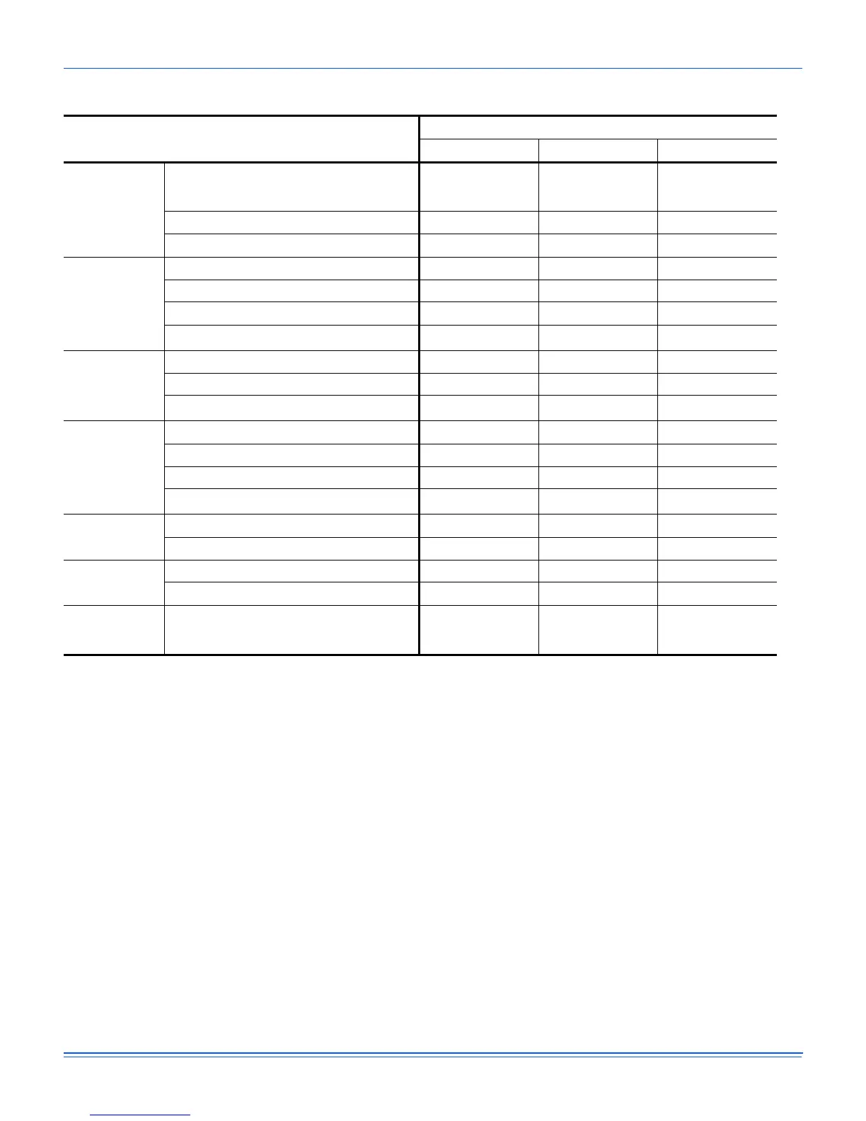
Table 14: PHYSICAL DATA
Component
1
1. R-407C units may require a super heat and sub-cooling check at the job site to ensure proper charge and operation.
Models
090 120 150
EVAPORATOR
BLOWER
Blower, Centrifugal
Dia. X Wd. in.
(Dia. X Wd. mm.)
12 X 12
(305 X 305)
15 X 15
(381 X 381)
15 X 15
(381 X 381)
Motor, Standard - HP (kW) 2 (1.5) 2 (1.5) 4 (3)
Motor, Optional - HP (kW) 2 (1.5) 4 (3) N/A
EVAPORATOR
COIL
Rows 2 3 4
Fins Per 2.54 cm (1 in.) 15 15 15
Height - in. (mm.) 32 (810) 40 (1020) 40 (1020)
Face Area ft.
2
(m
2
)
10.6 (0.98) 13.2 (1.23) 13.2 (1.23)
CONDENSER
FANS (2 per
Unit)
Propeller Dia. mm (in.) ea. 24 (610) 24 (610) 24 (610)
Motor - Hp (kW) ea. 3/4 (0.56) 3/4 (0.56) 3/4 (0.56)
Airflow - CFM (m
3
/s) ea.
3700 (1.75) 3700 (1.75) 3700 (1.75)
CONDENSER
COILS (2 per
Unit)
Rows (each) 1 1 2
Fins Per Inch (2.54 mm) 20 20 20
Height - in. (mm.) 28 (711) 44 (1120) 44 (1120)
Face Area ft.
2
(m
2
)
9.2 (.86) 14.5 (1.35) 14.5 (1.35)
Refrigerant
Charge
System 1 - lbs. (kg.) 4.75 (2.15) 6.0 (2.72) 11.0 (4.99)
System 2 - lbs. (kg.) 4.0 (1.81) 5.75 (2.61) 10.0 (4.54)
COMPRESSORS
Quantity 2 2 2
Type Recip Recip Scroll
AIR
FILTERS
Size
Wd. x Ht. x Thickness in.
(Wd. x Ht. x Thickness mm.)
25x 16 x 2
(635 x 406 x 51)
25x 20 x 2
(635 x 508 x 51)
25x 20 x 2
(635 x 508 x 51)

 Loading...