5353649-UIM-A-0617
5
For upflow or downflow applications (FC/MC Models):
These coils are factory shipped for installation in either upflow or down-
flow applications with a minor conversion.
1. Remove and reposition the coil duct flanges as shown in figure 5 if
needed.
2. Position the coil on the furnace opening (or the furnace on the coil
for downflow) as shown in Figure 6.
3. Place the ductwork over the coil (or furnace) duct flanges and
secure.
4. Check for air leakage between the furnace and coil casing and seal
appropriately. Three tie plates are provided with the coils. If
needed, secure the coil to the furnace using these tie plates.
5. See sections on “Refrigerant Line Connections” and “Condensate
Drain Connections” for further installation instruction.
For horizontal applications (MC models only):
MC model coils are supplied ready to be installed in a horizontal posi-
tion. A horizontal drain pan is factory installed.
1. Remove and reposition the coil duct flanges as shown in figure 5 if
needed.
2. Position the coil and furnace as shown in Figure 7.
3. Place the ductwork over the coil or furnace duct flanges and
secure.
4. Check for air leakage between the furnace and coil casing and seal
appropriately. Three mounting plates are provided with the coils.
The mounting plates must be used to secure the top edges of the
furnace and coil together. See figures 7 and 8.
5. See sections on “Refrigerant Line Connections” and “Condensate
Drain Connections” for further installation instruction.
FURNACE ASSEMBLY - PC
The PC coils are designed for installation on top of upflow furnaces
only.
If the coil is used with a furnace of a different size, use a 45° transition
to allow proper air distribution through the coil.
1. Remove and reposition the coil duct flanges as shown in figure 5 if
needed.
2. Position the coil casing over the furnace opening as shown in Fig-
ure 9.
3. Place the ductwork over the coil duct flange and secure.
4. Check for air leakage between the furnace and coil casing and seal
appropriately.
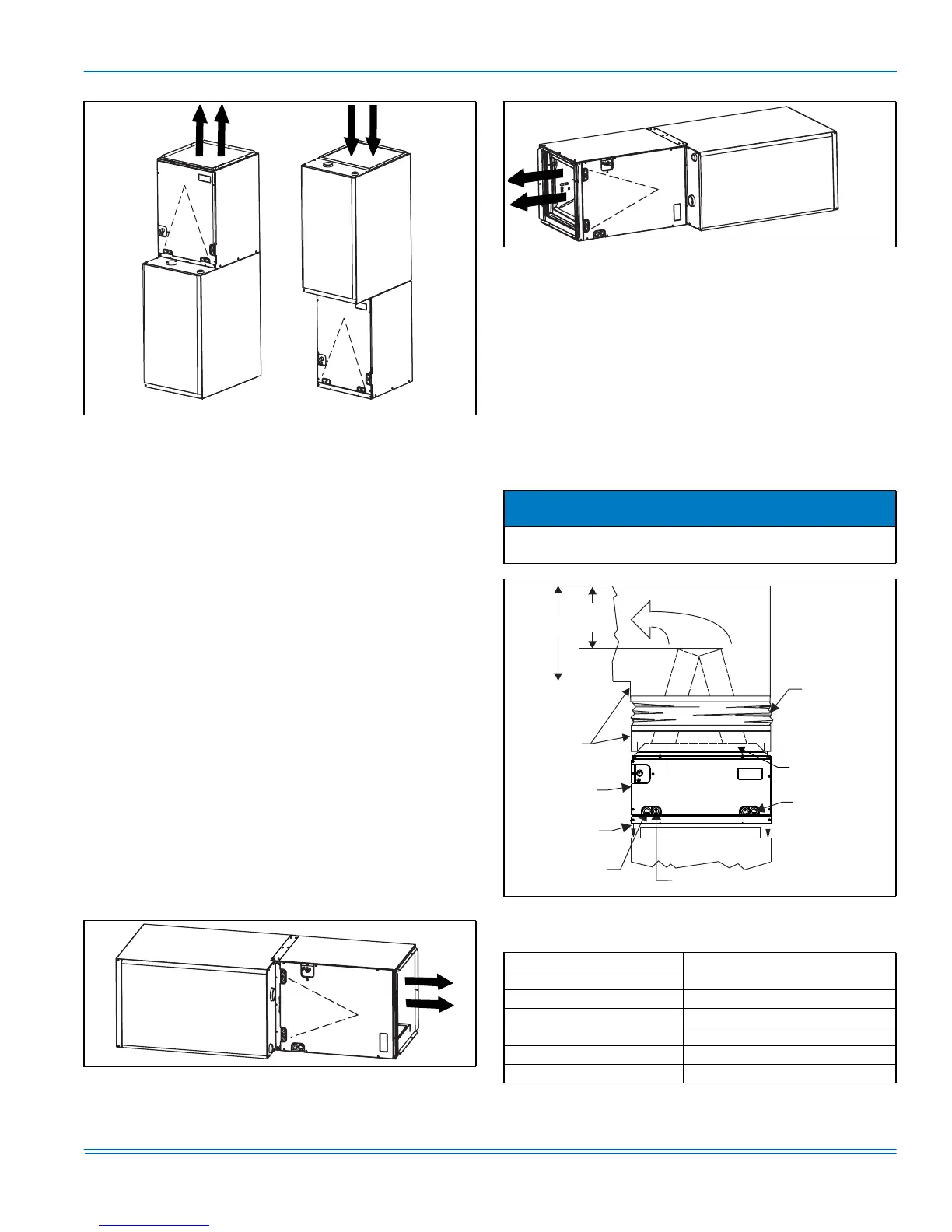
Dimension “C” should be at least 2/3 of dimension “D”. See Figure 9.
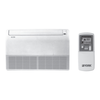
FIGURE 6: Vertical Applications with Furnaces
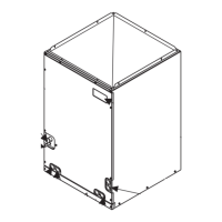
FIGURE 7: Horizontal Right Application with Furnaces
UPFLOW
DOWNFLOW
Furnace
Furnace
Furnace
FIGURE 8: Horizontal Left Application with Furnaces
NOTICE
Refer to the heat pump add-on control instruction before installing an
add-on heat pump coil.
FIGURE 9: Upflow - PC Coil Installation with Furnace
TABLE 5:
Coil Projection Dimensions - PC Coils
COIL SIZE DIMENSION “C” INCH
PC18 3-1/2
PC24 4-1/2
PC30, PC32, PC35 4-1/2
PC42, PC43, PC36, PC37 5-1/2
PC48 6-1/2
PC60 9
Furnace
Flexible Duct
Collar
DO NOT Drill or
Screw this Flange
Field
Fabricated
Ductwork
Upflow Coil
Upflow Furnace
Secondary Drain
Primary Drain
D
C
(Min.)
Alternate
Drain Location
 Loading...