5353649-UIM-A-0617
6
CRITICAL COIL PROJECTION
The coil assembly must be located in the duct such that a minimum dis-
tance is maintained between the top of the coil and the top of the duct.
Refer to Table 5.
SECTION V: DUCT CONNECTIONS
Air supply and return may be handled in one of several ways best
suited to the installation. Upflow, horizontal or downflow applications
may be used.
The vast majority of problems encountered with combination heating
and cooling systems can be linked to improperly designed or installed
duct systems. It is therefore highly important to the success of an instal-
lation that the duct system be properly designed and installed.
Use flexible duct collars to minimize the transmission of vibration/noise
into the conditioned space.
Where return air duct is short, or where sound may to be a problem,
sound absorbing glass fiber should be used inside the duct. Insulation
of duct work is a must where it runs through an unheated space during
the heating season or through an uncooled space during the cooling
season. The use of a vapor barrier is recommended to prevent absorp-
tion of moisture from the surrounding air into the insulation. The supply
air duct should be properly sized by use of a transition to match unit
opening. All ducts should be suspended using flexible hangers and
never fastened directly to the structure. Duct work should be fabricated
and installed in accordance with local and/or national codes. This
includes the standards of the National Fire Protection Association for
Installation of Air-Conditioning and Ventilating Systems, NFPA No. 90B.
SECTION VI: CONDENSATE DRAIN
CONNECTIONS
All drain lines should be pitched away from unit drain pan and should be
no smaller than the coil drain connection.
Route the drain line so that it doesn’t interfere with accessibility to the
coil, furnace, air handling system or filter and will not be exposed to
freezing temperatures.
Instruct the owner that the evaporator coil drain pan should be
inspected and cleaned regularly to prevent odors and assure proper
drainage.
Coils should be installed level or pitched slightly toward the drain end.
Suggested pitch should not exceed 1/4-inch per foot of coil.
If the coil is provided with a secondary drain it should be piped to a loca-
tion that will give the occupant a visual warning that the primary drain is
clogged. If the secondary drain is not used it must be capped.
DO NOT use Teflon
TM
tape, “pipe dope”, or other sealants. The use of
a sealant may cause damage and premature failure of the drain pan.
SUCTION FEEDER TUBE CONDENSATE
DEFLECTOR
Upflow or Downflow
No action required. See Figure 10.
Horizontal Left or Right
Use an appropriate tool to pry out water deflector with two or three s-
clips from the vertical drain pan. See Figure 11. Relocate the deflector
with s-clips on the Horizontal Drain Pan lined up to the coil support
bracket. See Figure 12. This positions the deflector below the feeder
tubes to channel the condensate to the drain pan.
WARNING
Use 1/2" screws to connect ductwork to unit. If pilot holes are drilled,
drill only through field duct and unit flange.
CAUTION
Equipment should never be operated without filters.
NOTICE
When the coil is installed in an attic or above a finished ceiling, an
auxiliary drain pan must be provided under the coil as is specified by
most local building codes.
CAUTION
Avoid Double Trapping.
!
!
!
CAUTION
Threaded drain connections should be hand tightened, plus no more
than 1 turn.
NOTICE
If the coil is installed in a draw-thru application (modular air handler),
it is recommended to trap the primary and secondary drain line. If the
secondary drain line is not used, it must be capped.
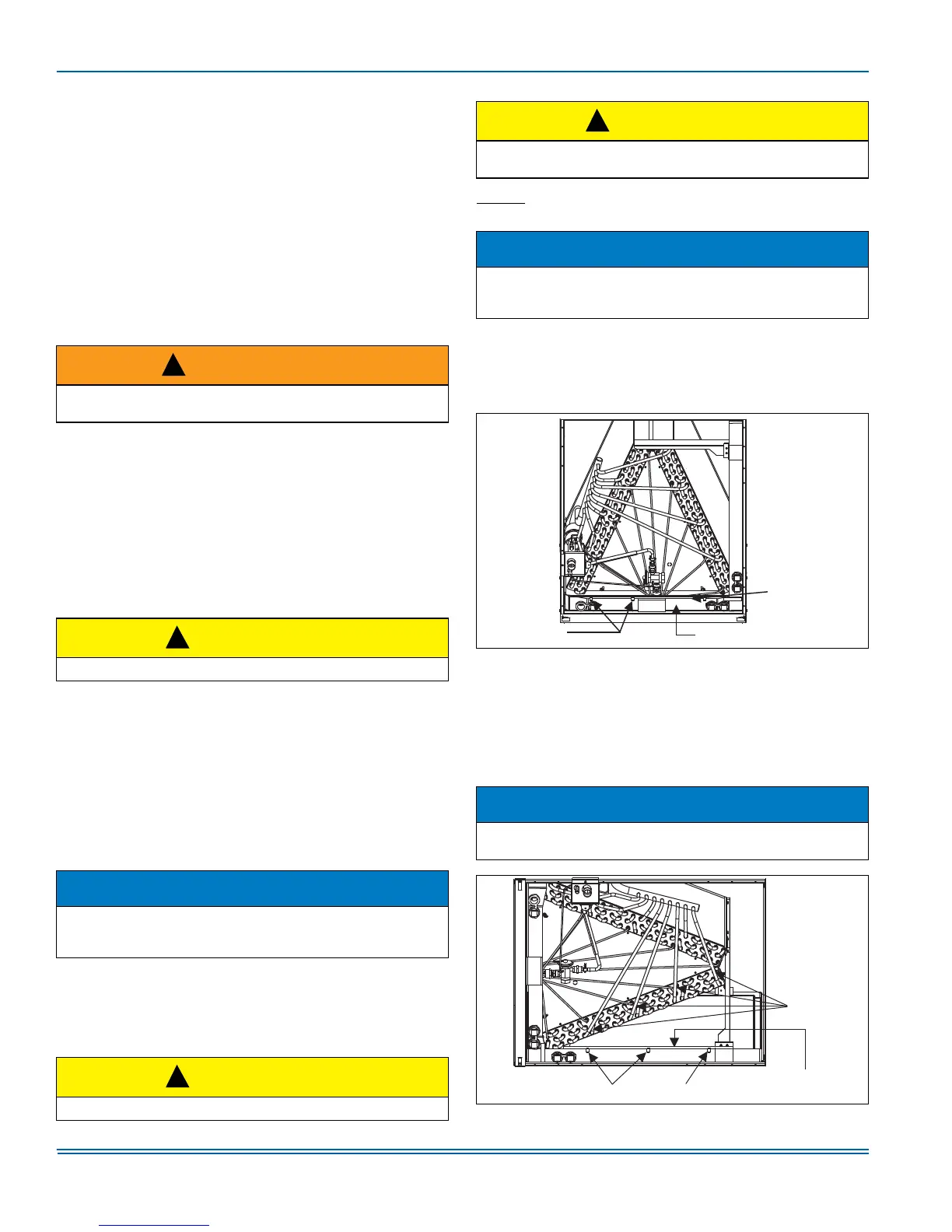
FIGURE 10: Condensate Deflector on Vertical Drain Pan
NOTICE
The condensate deflector should be installed in the s-clip section
which is inside the drain pan edge. See Figure 12.
FIGURE 11: Condensate Deflector on Horizontal Drain Pan Edge
!
Condensate
Deflector
S-Clips (3)
Vertical Drain Pan
S-Clips on Horizontal Pan
Feeder
Tubes
Condensate
Deflector
 Loading...