5353649-UIM-A-0617
7
SECTION VII: REFRIGERANT LINE
CONNECTION
Connect lines as follows:
1. Suction and liquid line connections are made outside the cabinet.
Leave the tubing connection panel attached to the cabinet with the
tubes protruding through it. Coil access panel should be removed
for brazing. The lines are expanded to receive the field line set
tubes.
2. Cut the end of the suction tube using a tube cutter. Place the tube
cutter as close as possible to the end of the tube to allow more
space for the connection and brazing of the suction line.
3. Wrap a water soaked rag around the coil connection tubes inside
the cabinet to avoid damaging the TXV bulb.
4. Remove grommets where tubes exit the cabinet to prevent burning
them during brazing.
5. Purge refrigerant lines with dry nitrogen.
6. Braze the suction and liquid lines.
7. Re-attach the grommets to the lines carefully to prevent air leak-
age.
8. Attach the coil access panel to the cabinet.
Refer to Outdoor unit Installation Manual for evacuation, leak check and
charging instructions.
Lines should be sound isolated by using appropriate hangers or strap-
ping.
All evaporator coil connections are copper-to-copper and should be
brazed with a phosphorous-copper alloy material such as Silfos-5 or
equivalent. DO NOT use soft solder.
SECTION VIII: COIL CLEANING
If the coil needs to be cleaned, it should be washed with Calgon Cal-
Clean (mix one part CalClean to seven parts water). Allow solution to
remain on coil for 30 minutes before rinsing with clean water. Solution
should not be permitted to come in contact with painted surfaces.
SECTION IX: AIR SYSTEM ADJUSTMENT
To check the CFM, measure the static pressure drop across the coil
using a portable manometer and static pressure tips. To prepare coil for
static pressure drop measurements - the system should have been
recently operational in cooling mode.
Drill 2 holes, one 3" after the coil (before any elbows in the ductwork)
and one 3” before the coil. Insert the pressure tips and read the pres-
sure drop from the manometer. See Table 4 to determine the air flow,
and make the necessary adjustments to keep the CFM within the air
flow limitations of the coil.
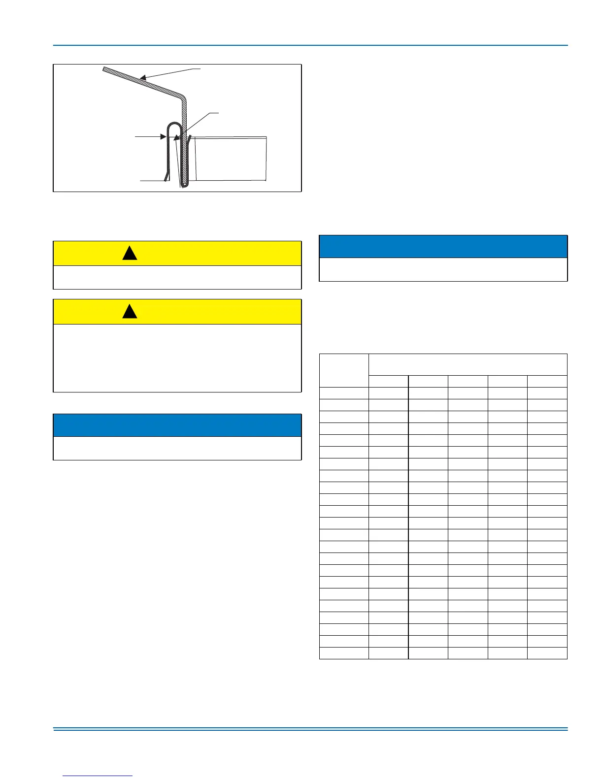
FIGURE 12: S-Clip Installation
CAUTION
Coil is under inert gas pressure. Relieve pressure from coil by remov-
ing rubber plug or by depressing schrader core.
CAUTION
Dry nitrogen should always be supplied through the tubing while it is
being brazed, because the temperature required is high enough to
cause oxidation of the copper unless an inert atmosphere is provided.
The flow of dry nitrogen should continue until the joint has cooled.
Always use a pressure regulator and safety valve to insure that only
low pressure dry nitrogen is introduced into the tubing. Only a small
flow is necessary to displace air and prevent oxidation.
NOTICE
Route the refrigerant lines to the coil in a manner that will not obstruct
service access to the coil, air handling system, furnace flue or filter.
Condensate
Deflector
S-Clip
Drain Pan
Wall
!
!
NOTICE
Table 6 below has WET coil data. Run system for approximately 15
minutes in cooling mode prior to taking measurements.
TABLE 6:
Air Flow Data - Static Pressure Drop
Coil Size
CFM @ Static Pressure Drop - IWG
(Based on wet coil)
0.10 0.15 0.20 0.25 0.30
18A 400 550 710 880 1000
18B 425 620 830 970 1125
24A 400 600 800 950 1075
24B 425 725 900 1075 1215
30A 425 600 800 950 1075
30B 450 725 900 1075 1215
32A 555 725 865 970 1080
35B 600 800 950 1090 1220
35C 792 1007 1206 1382 1572
36A 625 775 925 1025 1125
37A 689 880 1031 1180 1300
36B 825 976 1174 1300 1450
36C 975 1225 1375 1575 1775
38C 1020 1260 1470 1660 1818
42B 825 1000 1175 1325 1450
42C 1025 1275 1475 1650 1850
43C 785 1025 1210 1400 1570
48C 900 1075 1300 1475 1600
48D 1008 1224 1451 1620 1788
49D 1010 1360 1590 1790 1870
60D 1160 1432 1598 1750 1870
62D 1240 1532 1709 1870 2000
64D 1152 1362 1573 1783 1994
 Loading...