035-17480-000 Rev. A (800)
UnitaryProductsGroup 19
To install the vent drain, complete the following steps:
1. Place a tee of the proper diameter for the vent system
being installed (2" or 3") in the horizontal run closest to
the furnace.
2. Place a reducer bushing of proper diameter in the stem
portion of the tee. The recommended size for the
reducer is 5/8”.
3. Place a piece of 5/8” diameter or other selected size pipe
a minimum of 3" long into the reducer to serve as a
nipple.
NOTE
:Tee, reducer and nipple must be properly cemented
together using the appropriate method and materials speci-
fied in the Combustion Air Intake/Vent Connections section of
these instructions.
4. Connect a piece of flexible drain tubing such as EPDM
rubber, Vinyl or PVC to the nipple.
5. Loop the drain tubing to provide a trap.
6. Connect the discharge end of the drain tube to the con-
densate disposal system externally to the furnace.
CONDENSATE PIPING
The condensate drain connection is packed in the furnace for
field installation. It consists of a formed hose with a 1/2” NPT
male connection. A 1/2” FM x 3/4” PVC slip coupling is pro-
vided.
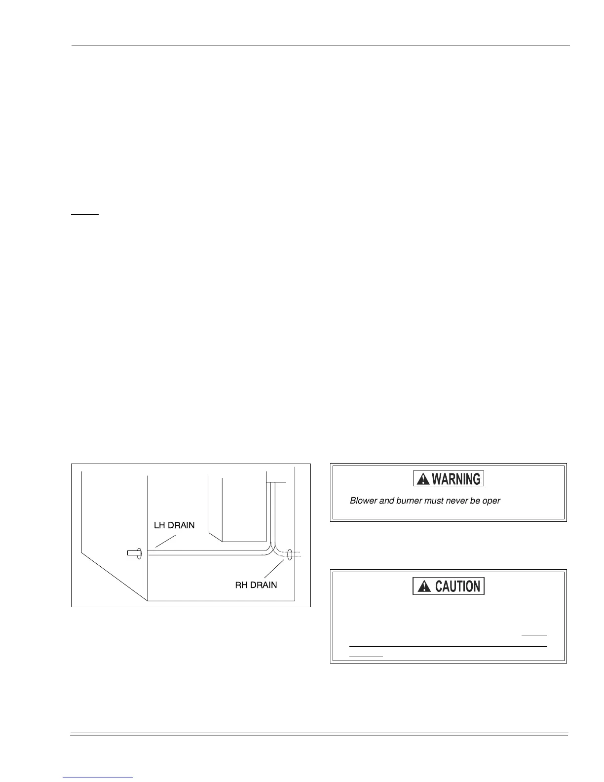
This drain hose may be installed to allow left or right side con-
densate drain connection, (refer to Figure 23). Cut the hose
to allow for proper fit for left or right exit.
To install the drain hose assembly, remove the 7/8” knockout
in the side panel. Remove the conduit nut from the 1/2” male
fitting. Push the male fitting through the hole and reinstall the
nut. The use of the 3/4” PVC coupling is optional.
Drain Connection: The following steps apply to all models.
1. It is recommended that either 1/2” or 3/4” PVC or equiva-
lent pipe be field installed as drain pipe. The condensate
piping may be tied together with the air conditioning con-
densate drain if the air conditioning condensate drain
line is trapped upstream of the tie-in and the combined
drains are constructed of the same material.
2. All pipe joints must be cleaned, de-burred and cemented
using PVC primer and cement.
3. The furnace contains an internal trap. Therefore, no
external trap should be used.
4. If a condensate pump is used, it must be suitable for use
with acidic water.
5. Where required, a field-supplied neutralizer can be
installed in the drain line, external to the furnace.
NOTE: The condensate drain from the furnace may be con-
nected in common with the drain from an air conditioning coil
if allowed by local code. Follow the instructions with the coil
for trapping the drain.
SAFETY CONTROLS
Control Circuit Fuse: A 3 amp. fuse is provided to protect
the 24 volt transformer from overload caused by control cir-
cuit wiring errors. This is an ATO 3, automotive type fuse and
is located in the unit wiring harness between the control
transformer and the furnace control.
Blower Door Safety Switch: This unit is equipped with an
electrical interlock switch mounted in the blower compart-
ment. This switch interrupts all power at the unit when the
panel covering the blower compartment is removed.
Electrical supply to this unit is dependent upon the panel that
covers the blower compartment being in place and properly
positioned.
FIGURE 23 : Upflow Models P*XU / G9D-UP
LHDRAIN
RH
DRAIN
Blower and burner must never be operated without
the blower panel in place.
Main power to the unit must still be interrupted at
the main power disconnect switch before any ser-
vice or repair work is to be done to the unit. Do not
rely upon the interlock switch as a main power dis-
connect.
 Loading...