035-17480-000 Rev. A (800)
22 Unitary Products Group
ADJUSTMENT OF MANIFOLD GAS PRESSURE
Manifold gas pressure may be measured by two different pro-
cedures. It may be measured with the burner box cover in
place or it may be measured with the burner box cover
removed. Follow the appropriate section, 1a or 1b in the
instructions below.
1. Read the inlet gas pressure using either of the two meth-
ods below.
a. Reading the gas pressure with the burner box
cover in place - Disconnect the pressure reference
hose from the right side of the burner box. Using a
tee fitting and a short piece of hose, connect the
negative side of the manometer to the burner box
pressure reference port. Connect the positive side
of the manometer to the adapter previously installed
in the gas valve ( Refer to Figure 27.)
b. Reading the gas pressure with the burner box
cover removed - Remove the screws securing the
burner box front cover plate. Remove the cover. It is
gasketed and may stick in place. Connect the posi-
tive side of the manometer to the adapter previously
installed in the gas valve as shown in Figure 27.
Therewillbenosecondconnectiontothemanome-
ter as it will reference atmospheric pressure.
The regulated outlet pressures, both low and high, have been
calibrated at the factory. Additional pressure adjustment
should not be necessary. If adjustment is necessary, set to
the following specifications. After adjustment, check for gas
leakage.
Low Outlet Pressure Adjustment
1. Turn off all electrical power to the system at main fuse or
circuit breaker.
2. Attach a manometer to the outlet pressure tap of the
valve.
3. Turn on power and energize main and redundant (P.M.)
solenoids. Do not energize HI terminal.
4. Remove low adjustment seal screw Figure 25 on
page 21.
5. To increase outlet pressure, turn the 3/32” socket set
screw below the low adjustment seal screw clockwise.
To decrease outlet pressure, turn the set screw counter-
clockwise. Adjust regulator until pressure shown on
manometer matches the pressure specified on the appli-
ance rating plate.
6. Replace low adjustment seal screw and tighten securely.
Cycle the valve several times to verify regulator setting.
7. Remove manometer and replace the outlet pressure tap
plug.
High Outlet Pressure Adjustment
1. Turn off all electrical power to the system at main fuse or
circuit breaker.
2. Attach a manometer to the outlet pressure tap of the
valve.
3. Turn on power and energize main and redundant (P.M.)
solenoids as well as the HI terminal.
4. Remove high adjustment seal screw to expose the 3/32”
socket set screw (refer to Figure 26).
Be sure to relight any gas appliance that were
turned off at the start of this input check.
Natural Gas Propane Gas
Low Fire 1.6 IWG 6.5 IWG
High Fire 3.5 IWG 10.0 IWG
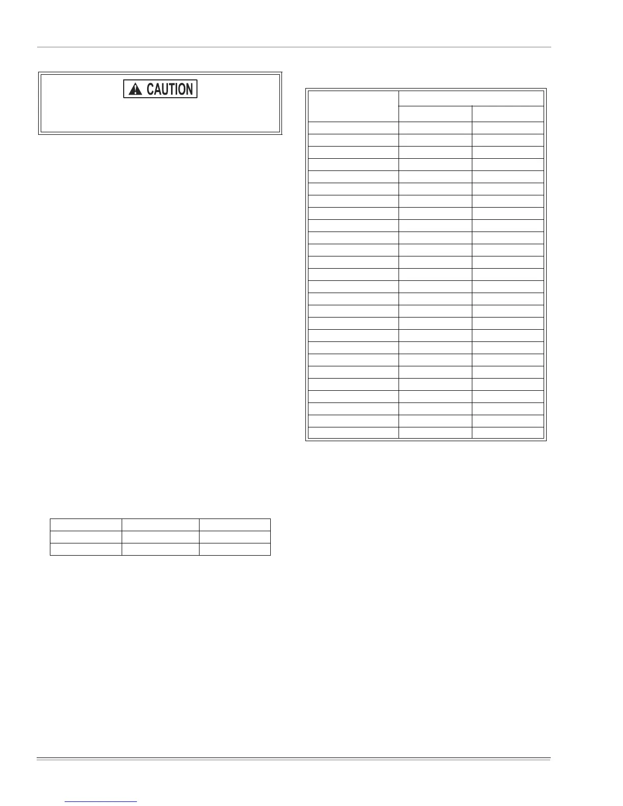
TABLE 6 : GAS RATE (CUBIC FEET PER HOUR)
SECONDS FOR ONE
REVOLUTION
SIZE OF TEST DIAL
1/2 CUBIC FOOT 1 CUBIC FOOT
10 180 360
12 150 300
14 129 257
16 113 225
18 100 200
20 90 180
22 82 164
24 75 150
26 69 138
28 64 129
30 60 120
32 56 113
34 53 106
36 50 100
38 47 95
40 45 90
42 43 86
44 41 82
46 39 78
48 37 75
50 36 72
52 35 69
54 34 67
56 32 64
58 31 62
60 30 60
 Loading...