035-17480-000 Rev. A (800)
20 Unitary Products Group
Rollout Switch Controls: These controls are mounted on
the burner box assembly. If the temperature in the burner
compartment exceeds its set point, the igniter control and the
gas valve are de-energized. The operation of this control indi-
cates a malfunction in the combustion air blower, heat
exchanger or a blocked vent pipe connection. Corrective
action is required. This is a manual reset control and must be
reset before operation can continue.
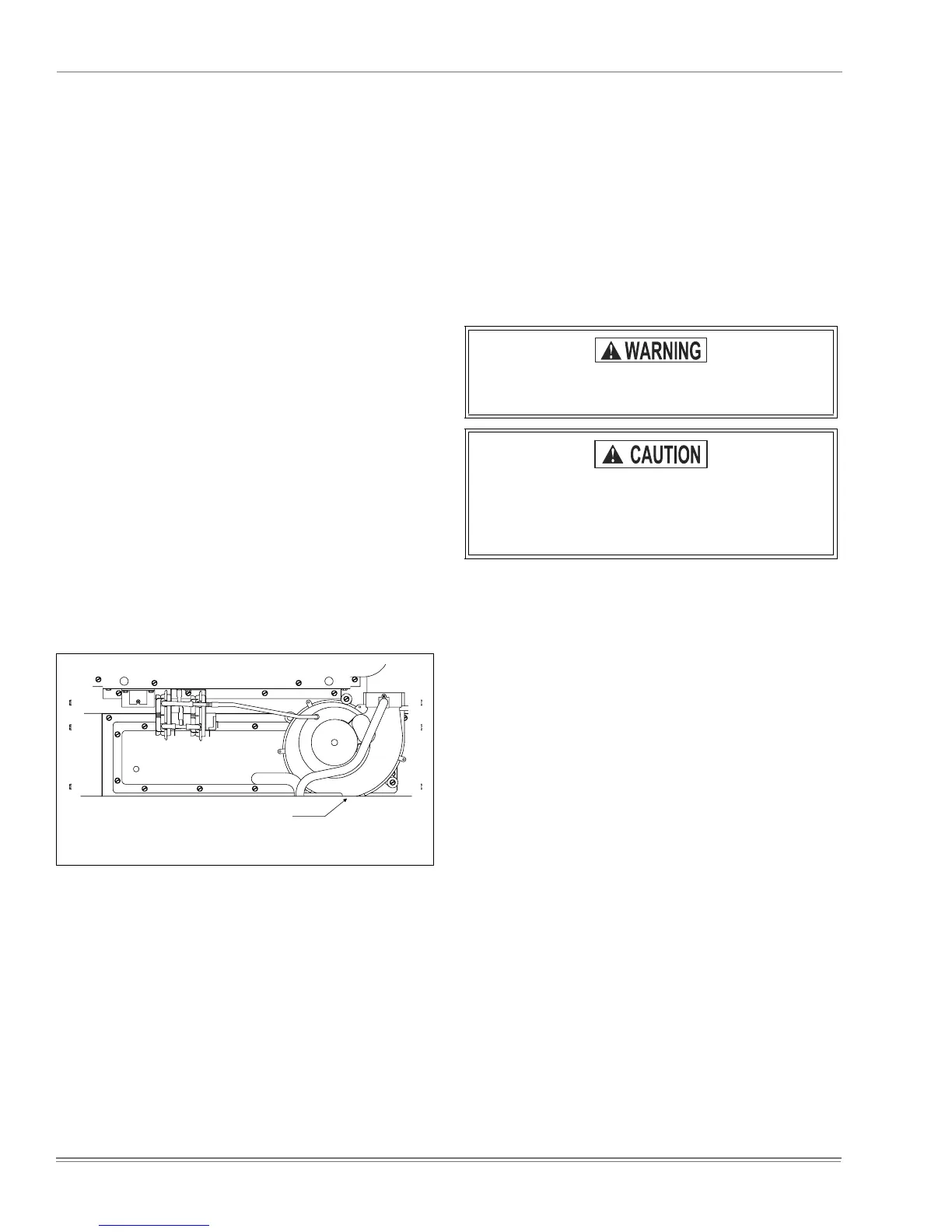
Pressure Switches: This furnace is supplied with pressure
switches which monitor the flow through the combustion air/
vent piping system. These switches de-energize the ignition
control module and the gas valve if any of the following condi-
tions are present. Refer to Figure 24 for tubing connections
1. Blockage of combustion air piping or terminal:
•Low fire (1LP)
•High fire (2 LP)
2. Blockage of vent piping or terminal:
•Low fire (1LP)
•High fire (2 LP)
3. Failure of combustion air blower motor :
•Low fire (1LP)
•High fire (2 LP)
4. Blockage of condensate drain piping:
•Low fire (1LP)
•High fire (2 LP).
Limit Control
There are high temperature limit controls located on the fur-
nace vestibule panel near the gas valve. These are automatic
reset controls that provide over temperature protection due to
reduced airflow, such as a dirty filter.
START-UP AND ADJUSTMENTS
The initial start-up of the furnace requires the following addi-
tional procedures:
1. When the gas supply is initially connected to the furnace,
the gas piping may be full of air. In order to purge this air,
it is recommended that the ground union be loosened
until the odor of gas is detected. When gas is detected,
immediately retighten the union and check for leaks.
Allow five minutes for any gas to dissipate before con-
tinuing with the start-up procedure.
2. The condensate trap must be filled with water before put-
ting the furnace into operation. The recommended pro-
cedure is as follows:
a. Disconnect the condensate drain hose from the
induced draft blower discharge.
b. Elevate this hose and fill with water using a funnel.
c. Replace the condensate drain hose and clamps.
NOTE: If this procedure is not followed, the unit may not
properly drain on initial start up.
3. All electrical connections made in the field and in the fac-
tory should be checked for proper tightness.
IGNITION SYSTEM SEQUENCE
1. Turn the gas supply ON at external valve and main gas
valve.
2. Set the thermostat above room temperature to call for
heat.
3. System start-up will occur as follows:
a. The induced draft blower motor will start and oper-
ate on low speed. Shortly after venter start-up, the
hot surface igniter will glow for about 17 seconds.
b. The ignition module will energize (open) the main
gas valve on low fire for seven seconds.
c. After flame is established, the supply air blower will
start in about 30 seconds.
FIGURE 24 : Pressure Switch Tubing Routing
INDUCTED DRAFT
BLOWER
BURNER BOX
UPFLOW
1LP
2LP
Be sure proper ventilation is available to dilute and
carry away any vented gas.
Perform the following procedures only after the
condensate trap has been properly piped to a
drain connection using the procedure in this
instruction.
 Loading...