035-17480-000 Rev. A (800)
UnitaryProductsGroup 23
5. To increase outlet pressure, turn the 3/32” socket set
screw clockwise. To decrease outlet pressure, turn the
set screw counterclockwise. Adjust regulator until pres-
sure shown on manometer matches the pressure speci-
fied on the appliance rating plate.
6. Replace high adjustment seal screw and tighten
securely. Cycle the valve two or three times to verify reg-
ulator setting.
7. Remove manometer and replace the outlet pressure tap
plug.
Once the correct gas pressure to the burners has been
established,turnthegasvalveknobtoOFFandturnthe
electrical supply switch to OFF; then remove the pressure tap
at the gas valve and re-install the plug, using a compound (on
the threads) resistant to the action of LP gases. Replace the
burner box front cover or the pressure reference hose.
Turn the electrical and gas supplies back on, and with the
burners in operation, check for gas leakage around the plug
with a soap and water solution.
ADJUSTMENT OF TEMPERATURE RISE
The temperature rise, or temperature difference between the
return air and the heated air from the furnace, must be within
the range shown on the furnace rating plate. Application limi-
tations are shown in Table 1 or 2. After the temperature rise
has been determined, the cfm can be calculated.
After about 20 minutes of operation, determine the furnace
temperature rise. Take readings of both the return air and the
heated air in the ducts, about six feet from the furnace where
they will not be affected by radiant heat.
Increase the blower speed to decrease the temperature rise;
decrease the blower speed to increase the rise.
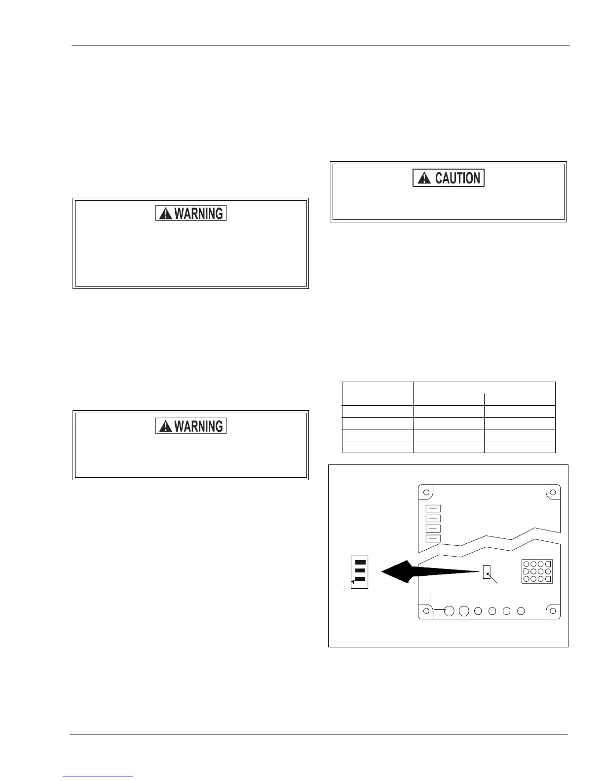
All direct-drive blowers have multi-speed motors. The blower
motor speed taps are located in the control box in the blower
compartment. Refer to Figure 28 and the unit wiring label to
change the blower speed.
You may select a heating speed and a cooling speed. They
may be the same speed or a different speed.
To use the same speed tap for heating and cooling, the heat
terminal and cool terminal must be connected using a jumper
wire and connected to the desired motor lead. Place all
unused motor leads on Park terminals. One Park terminal is
provided.
ADJUSTMENT OF FAN-OFF CONTROL SETTINGS
This furnace is equipped with a time-on/time-off heating fan
control. The fan on is fixed at 30 seconds. The fan off is field
adjustable from 60 to 180 seconds. The fan off is factory set
to 60 seconds. Adjust the off time by repositioning the fan off
switches. Figure 26 on page 23.
The fan-off setting must be long enough to adequately cool
the furnace, but not so long that cold air is blown into the
heated space. The fan-off timing may be adjusted by setting
the option switches located Figure 26 on page 23 on the
control board as follows:
If manifold pressure is too high, an over-fire condi-
tion exists which could cause heat exchanger fail-
ure. If the manifold pressure is too low, sooting
and eventual clogging of the heat exchanger could
occur.
Be sure that gas valve regulator cap and burner
box to gas valve pressure reference hose is recon-
nected.
Do not energize more than one motor speed at a
time or damage to the motor will result.
To Delay Fan-Off
By:
Set Switch
12
60 Sec. ON ON
90 Sec. OFF ON
120 Sec. ON OFF
180 Sec. OFF OFF
FIGURE 26 : Typical Heat/Cool Speed Tap Connections
COOL
HEAT LO
HEAT HI
OFF
ON
W1
W2
Y
R
G
B
FAN OFF
ADJUSTMENT
SWITCHES
LINE
Field Selectable
Continuous Fan Speed.
Cool or Heat Low.
 Loading...