DPC-1 thermostat
When a lockout is generated, and there is communication, the thermostat
indicates, alternatively, the time and failure produced, in accordance with
the lockout table of the unit.
Also indicates other incidences of the thermostat.
Incidence
Incidences are indicated by the green LED on the YKLON board. If no lockouts
exist, this LED flashes at a constant frequency.
When an incident is generated, this LED produces three series of flashes with
a constant sequence.
The first series indicates the affected circuit: one flash for the first compressor,
two for the second, three for the third and four for miscellaneous incidences.
This is followed by a brief pause. The second and third series indicate the
direct cause of the incidence.
Test button
- If pressed until the green LED goes on, certain timings are shortened and
any detected failure is reset.
- If pressed until the red LED goes on, two accessories and optional probes
connected to the board are identified.
- If there is communication between units and this button is pressed, the
Neuron ID is sent by the LonWorks network.
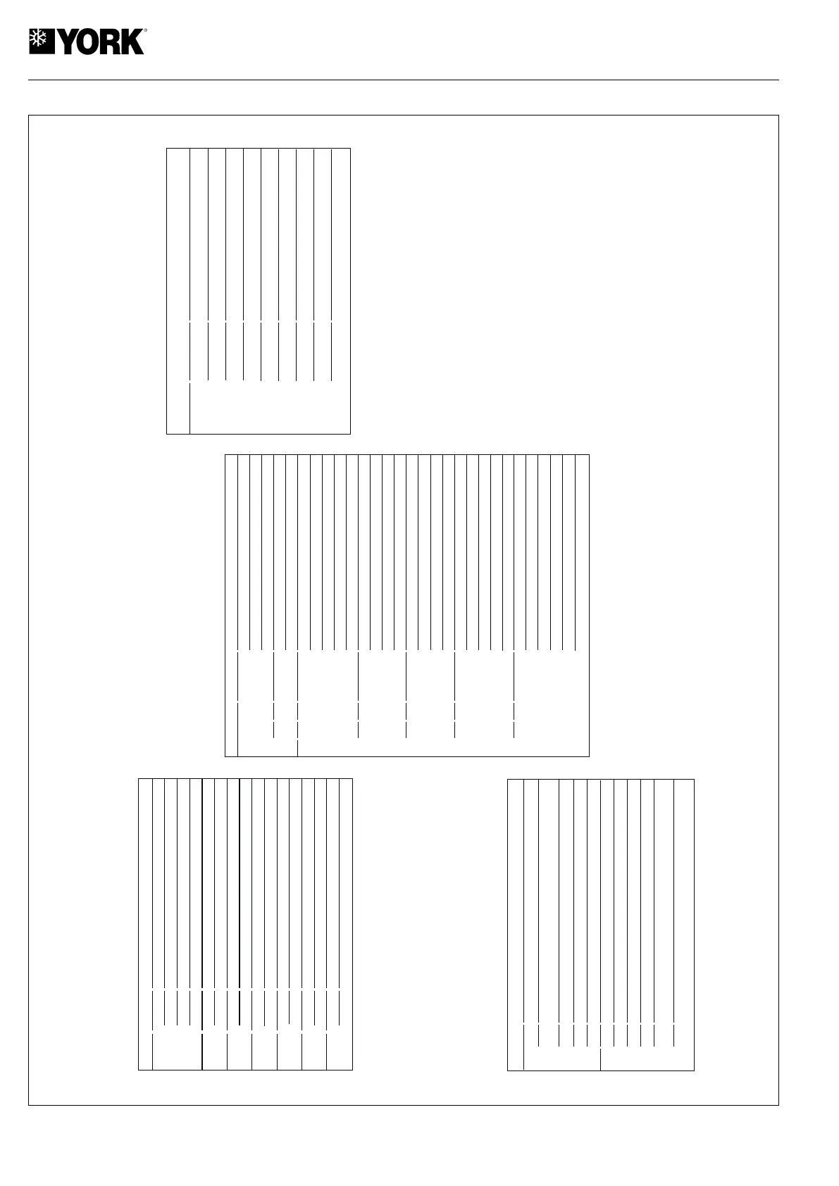
Incidence table
Flashes
Type
Probes
Occupation sensor in unoccupied
Probes
Aux. heat
Thermostat
Temperature
Discharge probe open or short circuited
Incidence
Liquid probe open or short circuited
Suction probe open or short circuited
Repeated defrosts
Discharge temperature not recovered
Discharge temperature not recovered
Return probe open or short circuited
Outdoor probe open or short circuited
Water probe open or short circuited
Enthalpy probe error
Signal Y1 or Y2 without G
Thermal switch of heater 1
Thermal switch of heater 2
Thermal switch of heater 3
Thermal switch of heater 4
Water coil temp. not recovered
Outdoor temp. too low
Water coil in antifreeze function
Impulse temp. over 55° C
Transceiver ID unknown
At least one accessory not found
Air quality demand
Dirty filters
4
1
2
ó
3
Signal W without B
Signal W without G
Signal Y2 without Y1
1
2
3
2
1
2
3
4
5
1
1
2
3
4
1
2
3
4
1
2
3
4
5
1
2
3
4
5
1
2
3
4
5
Others
Temperature
1
2
Thermostat
Communication error
9 3
External entry of failure9 4
Type
Thermostat
numbers
Incidence
Ambient probe open or short circuited
Internal probe not calibrated
9 1
9 2
Digital probe S7 is not detected
9 7
Digital probe S9 is not detected9 9
Digital probe S5 is not detected
Digital probe S6 is not detected
9 5
9 6
Digital probe S8 is not detected
9 8
It is necessary to disconnect power supply to the board to read the new
configuration.
Failures (Lockouts)
Lockouts are indicated by the red LED on the YKLON board. If no lockouts
exist, the LED remains off.
When a lockout is generated, this LED produces two series of flashes with
a constant sequence.
The first series indicates the affected circuit: one flash for the first compressor,
two for the second, three for the third and four for the accessories. This is
followed by a brief pause. The second series indicates the element or
situation producing the lockout.
Configuration of switches
The microswitches establish the following configurations:
Number
Meaning
Status
1 / 2
Ignore SW, programmed by communications
Time between defrosts 30'
Time between defrosts 60'
Time between defrosts 90'
Crossed coils
Independent coils
2' compressor delay
5' compressor delay
Cool mode
Heat pump mode
4-way valve active in heat
4-way valve active in cool
Receives signal B from thermostat (active in heat)
Receives signal O from thermostat (active in cool)
Fan operative during defrost
Fan inoperative during defrost
OFF/OFF
ON/OFF
OFF/ON
ON/ON
ON
OFF
ON
OFF
ON
OFF
ON
OFF
ON
OFF
ON
OFF
3
4
5
6
7
8
Lockout table (red LED)
Flashes
Discharge temperature surpassed.
High pressure switch, outdoor fan thermal switch or compressor
module thermal switch.
Low pressure switch.
Indoor fan thermal switch.
Repeated start-ups in cool or suction temperature <-25° C.
Gas 1 control or heater 1 failure
Gas 2 control or heater 2 failure
Heater 3 stage failure
Heater 4 stage failure
Failure in economiser or hot water coil (outdoor impulse probe,
water return)
Smoke detection or high temperature (accessories) or impulse
temperature > 80°C
Failure
1
2
3
4
5
1
2
3
4
5
6
4
1
2
ó
3
Impulse temp. < 25° C with gas
Suction temperature < 0°C, economiser
6
I-2367c
 Loading...