18
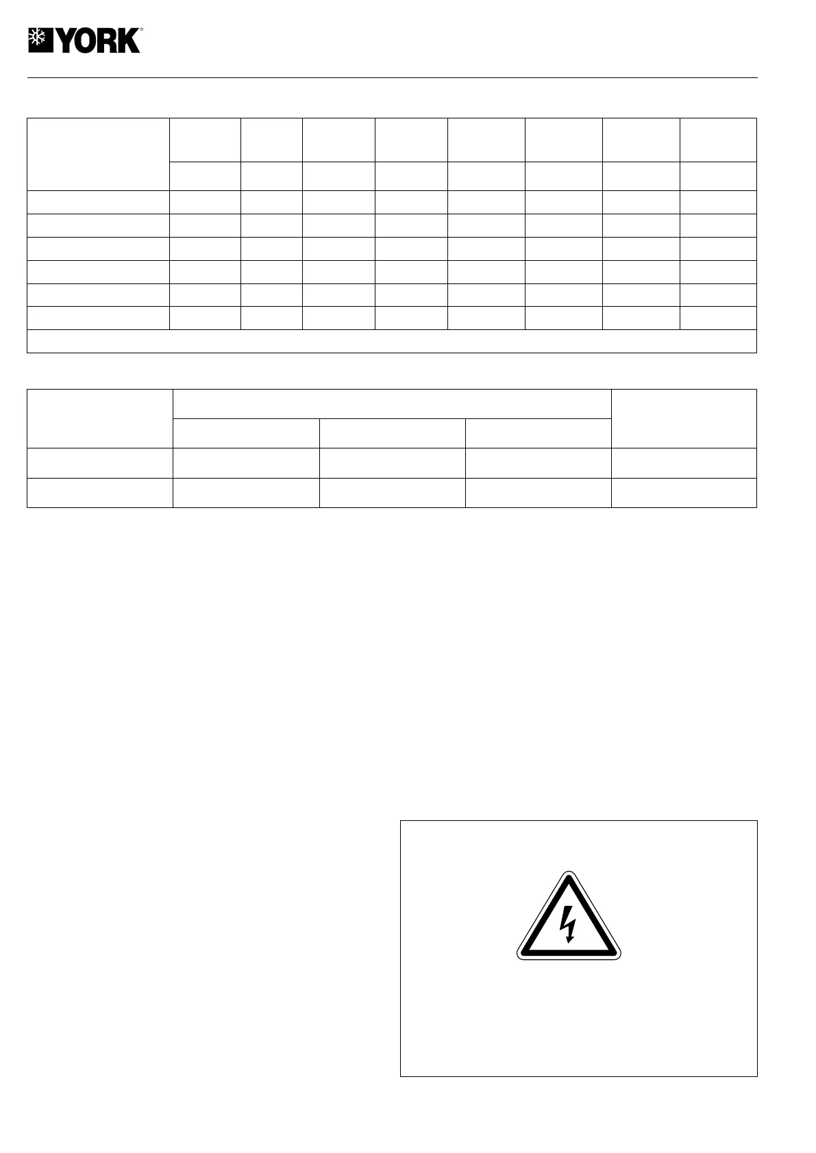
General characteristics
Dimensions with packing and weights
Installation
Install the electric heater in the RTC and RTH unit as fol-
lows:
1) In all cases, the established national regulations
should be followed.
2) Disconnect the power supply to the air conditioning
unit.
3) Install the magnetothermal and differential switches for
the heater in accordance with the table of General Char-
acteristics and the Wiring Diagrams.
4) Remove the access panels of the RTC and RTH unit
control box.
5) Unpack the accessory, opening the top of the box. Make
sure the heater assembly has not been damaged during
transportation. Check the ceramic insulation and that the
heater wires are not in contact with any metal parts.
6) Fit the electric heater in the mouth of the indoor fan panel
housing and drill eight 3 diameter holes for fastening.
Check to make sure that the reset push button of the F9
thermal switch is accessible and at the top. See Heater
Location diagram.
7) Fasten the PVC gasket, supplied with the accessory, to
the frame surface of the heater adjacent to the indoor fan
panel.
8) Fasten the heater to the panel with the screws sup-
plied.
9) Remove the electrical connections cover of the heater and
connect the power supply cables to connecting strip X1.
Connect the control cable supplied, between connector
J1 of the A3 Auxiliary Resistance board, and connector
J10 of the A1 control board of the air conditioning unit.
10) The installer should complete the electric circuit of the
heater by fitting an air flow control F14 at the most con-
venient point of the ducts so as to make sure the heater
operates only when there is sufficient air flow.
11) Connect power supply to the RTC and RTH unit and the
heater.
12) To configure the accessory, press the test button of con-
trol board A1 for over 2 seconds, until the red led on the
board goes on. Configuration will be complete when said
led goes off.
13) Check operation of the heater by selecting the Emergency
Heat mode at the ambient thermostat of the air condition-
ing unit.
14) Assemble the electrical box covers of the heater and the
RTC and RTH unit.
Note: Should an incorrect response of the system take place,
see the Operation section of the RTC and RTH Installation
Instructions. There you will find the control functions of the A1
electronic board on the heater, as well as its configuration,
incidents identification, etc.
Loose cables can cause overheating of the terminals or incorrect op-
eration of the unit. Fire hazards may also arise. Therefore, make sure
all cables are connected tightly.
Heater
model
Dimensions with packing mm
Weight
kg
Height Width Depth
RTC and RTH07L and 10L
360 513 293 15
RTC and RTH15L to 30L
440 640 370 20
Model
Power supply Power Consumption Stages
Automatic
switch (1)
Q1
Power
supply cable
section (2)
Front
furface
Pressure
drop (3)
V.ph.Hz kW A A mm
2
m
2
Pa
RTC and RTH07L
230.1.50 5 22 1 25 4 0.12 6
RTC and RTH07L to 10L
400.3.50 5 8 1 10 2.5 0.12 6
RTC and RTH07L to 10L
400.3.50 10 15 1 20 2.5 0.12 6
RTC and RTH15L to 30L
400.3.50 5 8 1 10 2.5 0.12 6
RTC and RTH15L to 30L
400.3.50 10 15 1 20 2.5 0.19 15
RTC and RTH15L to 30L
400.3.50 15 22 1 25 4 0.19 15
Notes: 1.- K curve (DIN. VDE 0660-104). 2.- Based on copper conductors. 3.- Considered the nominal air flow of the indoor section.
 Loading...