The “TH1" closes, the draft motor control ”DMC or ETD" is
energized. The “DMC” power contact closes which energizes
the line voltage draft motor. As the speed of the draft motor
reaches approximately 2500 RPM, the centrifugal switch
contact located on the end of the draft motor shaft closes to
power the ignition control “IC”.
After 15 seconds, the “IC” will start the ignitor sparking and will
open the redundant valve located inside the main gas valve
“GV” to allow a flow of gas to only the carryover tube. See Figure
11. Only after the pilot flame has been ignited and the presence
of pilot flame detected at the “IC” by a signal sent back through
the flame sensor is sparking terminated and the main gas valve
opened.
Gas flows into each of the main burners and is ignited from the
carryover tube flame.
If “IC” fails to detect a pilot flame, it will continue to try for a
maximum of 85 seconds to ignite the pilot tube. If the pilot flame
is not detected, then “IC” will soft lock out for 5 minutes. If the
pilot flame is not detected after 16 retries, then “IC” will hard
lock out the first stage furnace operation until 24V power is
removed from the module either at the unit or by resetting the
room thermostat.
At the same time power was supplied to the “DMC”, a parallel
circuit activates “BT” which closes “BT-1” after approximately
16 seconds and energizes “K5" which closes ”K5-2" and starts
the blower by energizing “M3”.
When “TH2" closes calling for second stage heating, it
energizes ”W2" on the gas valve “GV” directly.
When the heating cycle is complete, “TH-1" opens
de-energizing the ”DMR" and “IC”, thus closing the redundant
and main gas valves. The blower motor continues to run
(approximately 45 seconds after the furnace is shut down) until
“TDR” opens de-energizing the “K5" and ”3M" relays.
SAFETY CONTROLS
The control circuit includes the following safety controls:
1. Limit Control (LS). This control is located inside the heat
exchanger compartment and is set to open at the
temperature indicated in the Limit Control Table. It resets
automatically. The limit switch operates when a high
temperature condition, caused by inadequate supply air
flow occurs, thus shutting down the ignition control and
closing the main gas valve and energizing the blower.
2.
Centrifugal Switch (CS). If the draft motor should fail, the
centrifugal switch attached to the shaft of the motor pre-
vents the ignition control and gas valve from being ener-
gized.
3. Redundant Gas Valve. This valve is an integral part of the
main gas valve and is located up stream of the main gas
valve. Should the main gas valve fail in the open position
the redundant valve serves as a back up and shuts off the
flow of gas.
4. Flame Sensor Rod. This sensor rod is located on the far
side of the carryover tube. If the ignition control does not
receive a signal from the flame sensor indicating that the
pilot flame has ignited properly, the main gas valve will not
open. If the flame sensor fails to detect the pilot flame during
operation of the main burners, a signal is sent to the ignition
control to close the main gas valve.
5. Auxillary Limit Switch (AUX) This control is located insdie
thehet exchanger compartment and is set toopen a at
180
°
F. It is a manual reset switch. If Aux limit trips then the
primary limit has not functioned correctly. Replace the
primary limit.
6. Rollout Switch. This switch is located in the burner
vestibule. In the event of a sustained main burner flame
rollout, it shuts off the ignition control and closes the main
gas valve.
HEAT ANTICIPATOR SETPOINTS
It is important that the anticipator setpoint be correct. Too high
of a setting will result in longer heat cycles and a greater
temperature swing in the conditioned space. Reducing the
value below the correct setpoint will give shorter “ON” cycles
and may result in the lowering of the temperture within the
conditioned space.
Units
(Tons)
Capacity, MBH
Limit Control
Opens,
°
F
Input Output
7-1/2, 8-1/2
7-1/2, 8-1/2
10, 12-1/2
10, 12-1/2
163
204
204
245
130
163
163
198
180
170
170
170
TABLE 11
- LIMIT CONTROL SETTING
Gas Valve
Anticipator Setpoint
1st Stage 2nd Stage
Honeywell
VR8520
0.50 amp 0.24 amp
White-Rodgers
36C76
0.60 amp 0.10 amp
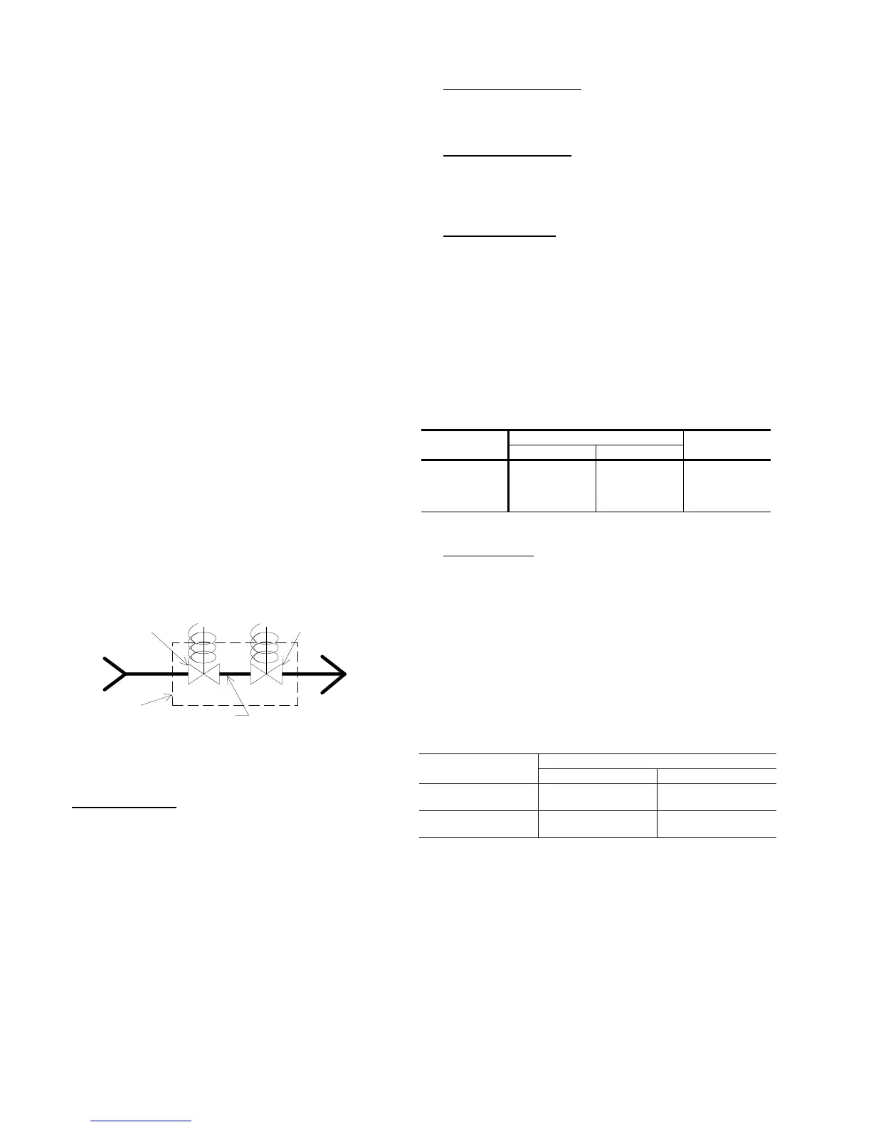
GAS
VALVE
GAS MAIN
MAIN VALVE
TO MAIN
BURNER
REDUNDANT
VALVE
TO PILOT BURNER
FIG. 11
- GAS VALVE PIPING
530.18-N10Y
14 Unitary Products Group
 Loading...