General ................................................................................ 1
Inspection............................................................................. 1
Reference ............................................................................ 1
Approvals............................................................................. 1
Nomenclature....................................................................... 2
INSTALLATION
Limitations............................................................................ 3
Location ............................................................................... 3
Rigging and Handling .......................................................... 3
Clearances........................................................................... 3
Ductwork .............................................................................. 3
Condensate Drain................................................................ 4
Compressors........................................................................ 4
Filters ................................................................................... 4
Service Access..................................................................... 4
Thermostat........................................................................... 4
Power and Control Wiring.................................................... 4
Combustion Discharge ........................................................ 5
Gas Piping ........................................................................... 5
Gas Connection................................................................... 5
L.P. Units, Tanks and Piping ................................................ 6
Vent and Combustion Air Hoods.......................................... 6
Optional Economizer ........................................................... 6
OPERATION
Cooling System.................................................................. 13
Preliminary Operation Cooling........................................... 13
Cooling Sequence of Operation......................................... 13
Safety Controls (Cooling)................................................... 13
Heating Sequence of Operation ........................................ 13
Safety Controls (Heating) .................................................. 14
Heat Anticipator Setpoints ................................................. 14
Pre-Start Check List........................................................... 14
START-UP
Operating Instructions........................................................ 15
Post-Start Check List......................................................... 15
Manifold Gas Pressure Adjustment ................................... 15
Pilot Checkout.................................................................... 15
Burner Instructions............................................................. 15
Burner Air Shutter Adjustment ........................................... 16
Checking Supply Air CFM.................................................. 16
Adjustment of Temperature Rise ....................................... 17
Checking Gas Input ........................................................... 17
Secure Owner’s Approval .................................................. 17
MAINTENANCE & TROUBLESHOOTING
Normal Maintenance.......................................................... 18
Cleaning Flue Passages and Heating Elements............... 18
Troubleshooting ................................................................. 19
Replacement Parts ............................................................ 20
TABLES
No. Description Page
1 Unit Application Data .................................. 3
2 Gas Heat Application Data.......................... 5
3 Pipe Sizing.................................................. 5
4 Physical Data.............................................. 8
5 Point Loads................................................. 10
6 Supply Air Blower Perf. 7-1/2 - 10 Ton........ 11
7 Supply Air Blower Perf. 12-1/2 Ton............. 12
8 Accessory Static Resistances .................... 12
9 Blower Motor and Drive Data...................... 12
10 Electrical Data............................................. 13
11 Limit Control Setting ................................... 14
12 Blower Motor Pulley Adjustment................. 16
13 Gas Rate - Cubic Feet Per Hour ................ 17
FIGURES
No. Description Page
1 Center of Gravity......................................... 3
2 Recommended Drain Piping....................... 4
3 Typical Field Wiring..................................... 5
4 External Supply Connection ....................... 6
5 Bottom Supply Connection ......................... 6
6 Vent and Combustion Air Hoods................. 6
7 Economizer................................................. 7
8 Adjusting Enthalpy Setpoint........................ 8
9 Dimensions and Clearances....................... 9
10 Point Loads................................................. 10
11 Gas Valve Piping......................................... 14
12 Typical Gas Valve ....................................... 15
13 Proper Flame Adjustment........................... 15
14 Typical Flame Appearance ......................... 16
15 Pressure Drop versus Supply Air CFM....... 16
TABLE OF CONTENTS
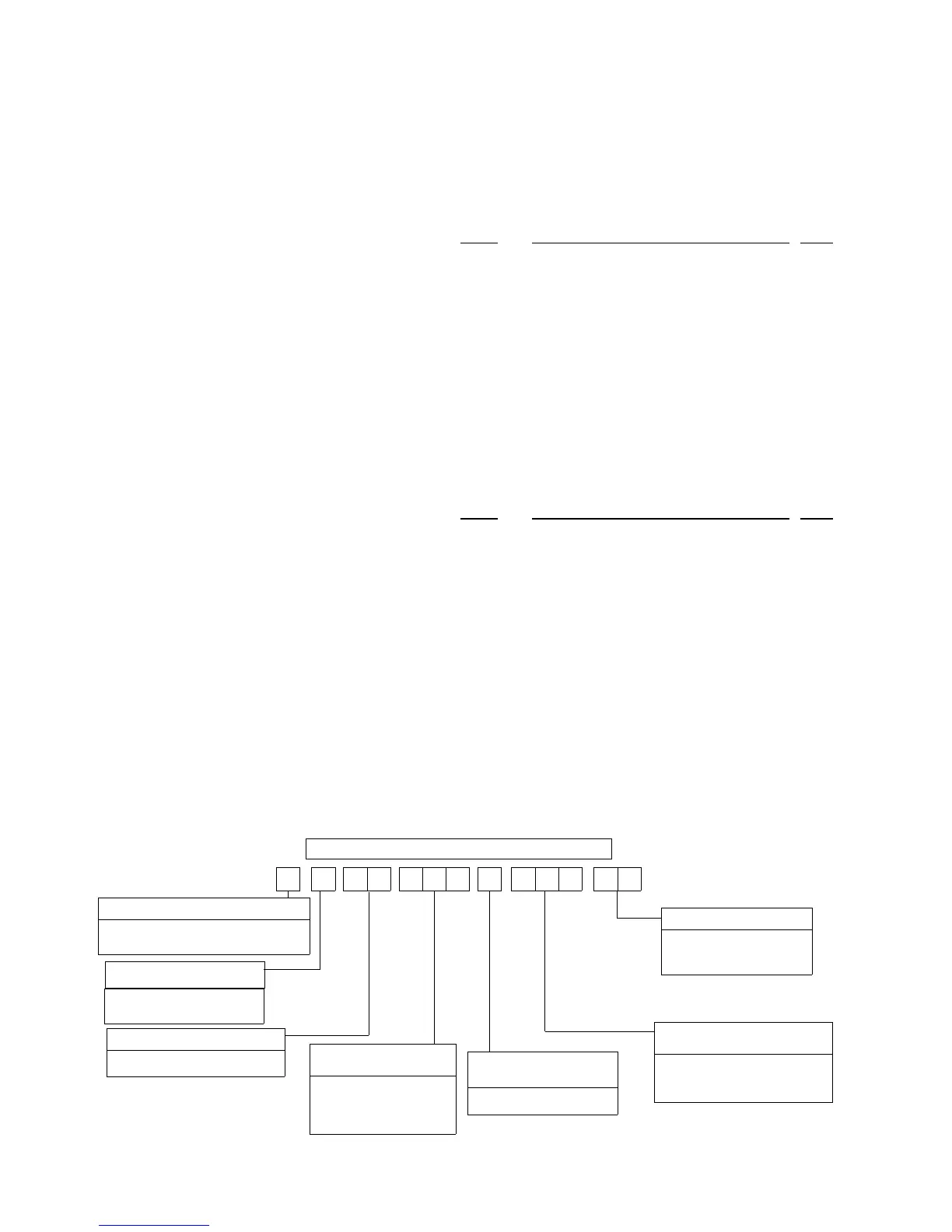
D 3 C G 3N
PRODUCT NOMENCLATURE
PRODUCT GENERATION
3 = 3rd Generation
4 = 4th Generation
PRODUCT CATEGORY
D = Single Package Air Conditioner
(Air Cooled)
PRODUCT IDENTIFIER
CG = Gas/Electric
VOLTAGE CODE
25 = 208/230-3-60
46 = 460-3-60
58 = 575-3-60
NOMINAL GAS HEATING
OUTPUT CAPACITY
090 = 7-1/2 Ton
102 = 8-1/2 Ton
120 = 10 Ton
150 = 12-1/2 Ton
1 090 0 2 5
FACTORY INSTALLED
HEAT
N = Gas Heat Installed
NOMINAL COOLING
CAPACITY
130 = 130 MBH
165 = 163 MBH
200 = 198 MBH
530.18-N10Y
2 Unitary Products Group
 Loading...