290699-YIM-B-0607
Unitary Products Group 15
GAS PIPING
Proper sizing of gas piping depends on the cubic feet
per hour of gas flow required, specific gravity of the gas
and the length of run. “National Fuel Gas Code” Z223.1
(in U.S.A.) or the current Gas Installation Codes CSA-
B149.1 (in Canada) should be followed in all cases
unless superseded by local codes or gas utility require-
ments. Refer to the Pipe Sizing Table 5.
The heating value of the gas may differ with locality.
The value should be checked with the local gas utility.
NOTE: There may be a local gas utility requirement
specifying a minimum diameter for gas piping.
All units require a 1/2” pipe connection at the
entrance fitting.
GAS CONNECTION
The gas supply line can be routed through the knock-
outs located on the front of the unit or through the
opening provided in the unit's base. Refer to Figure 11
to locate these access openings. Typical supply piping
arrangements are shown in Figures 4 and 5. All
shaded items are field-supplied.
If gas supply line is routed through the unit's base
ensure that the burner assembly can be removed for
maintenance without disturbing the supply line. The
supply piping and fittings must lie below the bottom gas
manifold to avoid interference with the burner assem-
bly.
Two grommets are shipped in the blower compartment
(in parts bag taped to the blower housing) of every unit
with gas heat and should be used in the knockouts
when the gas piping penetrates the front of the unit.
After the gas supply piping has been installed, the bot-
tom opening in the unit should be sealed to prevent
water from leaking into the building.
Gas piping recommendations
:
1. A drip leg and a ground joint union must be
installed in the gas piping.
2. When required by local codes, a manual shut-off
valve may have to be installed outside of the unit.
3. Use wrought iron or steel pipe for all gas lines. Pipe
compound should be applied sparingly to male
threads only.
4. All piping should be cleaned of dirt and scale by
hammering on the outside of the pipe and blowing
out the loose dirt and scale. Before initial start-up,
be sure that all of the gas lines external to the unit
have been purged of air.
5. The gas supply should be a separate line and
installed in accordance with all safety codes as
prescribed under “Limitations”. After the gas con-
nections have been completed, open the main
shut-off valve admitting normal gas pressure to the
mains. Check all joints for leaks with soap solution
or other material suitable for the purpose. NEVER
USE A FLAME.
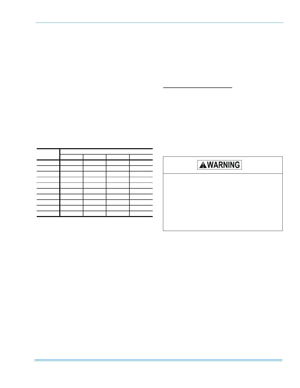
TABLE 5: GAS PIPE SIZING
1/2 in. 3/4 in. 1 in. 1-1/4 in.
10 132 278 520 1,050
20 92 190 350 730
30 73 152 285 590
40 63 130 245 500
50 56 115 215 440
60 50 105 195 400
70 46 96 180 370
80 43 90 170 350
90 40 84 160 320
100 38 79 150 305
NOMINAL IRON PIPE SIZE
LENGTH IN
FEET
Maximum capacity of pipe in cubic feet of gas per hour. (Based upon
a pressure drop of 0.3 inch water column and 0.6 specific gravity gas).
Natural gas may contain some propane. Pro-
pane, being an excellent solvent, will quickly
dissolve white lead or most standard commer-
cial compounds. Therefore, a special pipe
compound must be applied when wrought iron
or steel pipe is used. Shellac base compounds
such as Gaskolac or Stalastic, and compounds
such as Rectorseal #5, Clyde's or John Crane
may be used.
 Loading...