EasyManua.ls Logo

York SUNLINE DCG Series User Manual

York SUNLINE DCG Series
56 pages
To Next Page IconTo Next Page
To Previous Page IconTo Previous Page
Page #48 background imageLoading...
Page #48 background image
290699-YIM-B-0607
48 Unitary Products Group
NOTE: To find the Btu input, multiply the number of
cubic feet of gas consumed per hour by the
Btu content of the gas in your particular locality
(contact your gas company for this information
- it varies widely from city to city.)
ADJUSTMENT OF TEMPERATURE RISE
The temperature rise (or temperature difference
between the return air and the heated air from the fur-
nace) must lie within the range shown on the rating
plate and the data in the Gas Heat Application Table 4.
After the temperature rise has been determined, the
cfm can be calculated as follows:
After about 20 minutes of operation, determine the fur-
nace temperature rise. Take readings of both the return
air and the heated air in the ducts (about six feet from
the furnace) where they will not be affected by radiant
heat. Increase
the blower cfm to decrease the tempera-
ture rise; decrease
the blower cfm to increase the rise.
Refer to the Blower Motor and Drive Data Table 25.
TROUBLESHOOTING
COOLING TROUBLESHOOTING GUIDE
On calls for cooling, if the compressors are operating
but the supply air blower motor does not energize after
a short delay (the room thermostat fan switch is in the
“AUTO” position).
1. Turn the thermostat fan switch to the ON position.
If the supply air blower motor does not energize, go
to Step 3.
2. If the blower motor runs with the fan switch in the ON
position but will not run after the compressor has
energized when the fan switch is in the AUTO posi-
TABLE 31: GAS RATE - CUBIC FEET PER HOUR
1
1.
By actual measurement, it takes 38 seconds for the hand on
the 1-cubic foot dial to make a revolution with a 100,000
Btuh furnace running. Using this information, located 38
seconds in the first column in the table above. Read across
to the column headed “1 Cubic Foot”, where you will see
that 95 cubic feet of gas per hour are consumed by the fur-
nace at that rate. Multiply 95 X 1050 (the Btu rating of the
gas obtained from the local gas company). The result is
99,750 Btuh, which is close to the 100,000 Btuh rating of the
furnace.
Seconds for one
rev.
Size of Test Dial
1/2 cu. ft. 1 cu. ft.
10 180 360
12 150 300
14 129 257
16 113 225
18 100 200
20 90 180
22 82 164
24 75 150
26 69 138
28 64 129
30 60 120
32 56 113
34 53 106
36 50 100
38 47 95
40 45 90
42 43 86
44 41 82
46 39 78
48 37 75
50 36 72
52 35 69
54 34 67
56 32 64
58 31 62
60 30 60
Troubleshooting of components may require
opening the electrical control box with the power
connected to the unit. Use extreme care when
working with live circuits! Check the unit
nameplate for the correct line voltage and set
the voltmeter to the correct range before making
any connections with line terminals.
Shut off all electric power to the unit prior to
any of the following maintenance procedures
to prevent personal injury.
Label all wires prior to disconnection when ser-
vicing controls. Wiring errors can cause
improper and dangerous operation, which could
cause injury to person and/or damage unit com-
ponents. Verify proper operation after servicing.
CFM
Btuh Input x 0.8
=
108..xFTempRise
o

Table of Contents

Question and Answer IconNeed help?

Do you have a question about the York SUNLINE DCG Series and is the answer not in the manual?
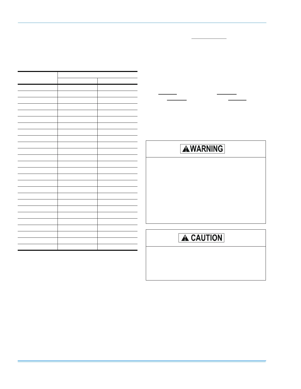
York SUNLINE DCG Series Specifications

General IconGeneral
RefrigerantR410A
SeriesSUNLINE DCG Series
Energy Efficiency Ratio (EER)Varies by model
Coefficient of Performance (COP)Varies by model
Indoor Unit Dimensions (HxWxD)Varies by model
Outdoor Unit Dimensions (HxWxD)Varies by model
Indoor Unit WeightVaries by model
Outdoor Unit WeightVaries by model

Summary

GENERAL

SAFETY CONSIDERATIONS

FIRE OR EXPLOSION HAZARD

Critical warning on gas and flammable materials.

INSPECTION

REFERENCE AND APPROVALS

PRODUCT NOMENCLATURE

INSTALLATION

INSTALLATION SAFETY INFORMATION

Critical safety steps before starting installation.

LIMITATIONS

Codes and standards for installation compliance.

LOCATION AND HANDLING

CLEARANCES

Required distances for operation and service access.

DUCTWORK AND DRAINAGE

CONDENSATE DRAIN

Requirements for plumbing the condensate drain line.

COMPRESSORS

FILTERS AND SERVICE ACCESS

ELECTRICAL WIRING

ELECTRIC HEAT WIRING

Specifics on installing field-installed electric heaters.

GAS HEAT OVERVIEW

GAS PIPING AND CONNECTION

L.P. GAS SYSTEMS

VENT AND COMBUSTION AIR HOODS

ECONOMIZER AND EXHAUST OPTIONS

References for economizer and power exhaust installation.

ECONOMIZER AND EXHAUST DAMPER ADJUSTMENTS

MINIMUM POSITION ADJUSTMENT

Procedure to set the minimum damper position.

ENTHALPY SET POINT ADJUSTMENT

How to set the enthalpy set point for economizer control.

POWER EXHAUST DAMPER SETPOINT (WITH OR WITHOUT POWER EXHAUST)

Procedure for setting the power exhaust damper.

PHASING AND BELT TENSION

PROCEDURE FOR ADJUSTING BELT TENSION

Detailed steps for adjusting belt tension.

SUPPLY AIR BLOWERS

CHECKING SUPPLY AIR CFM

OPERATION

SEQUENCE OF OPERATIONS OVERVIEW

General overview of unit operation logic.

COOLING SEQUENCE OF OPERATION

Detailed steps for unit operation in cooling mode.

COOLING OPERATION ERRORS

How the system handles cooling malfunctions.

COMPRESSOR SAFETY CONTROLS

LOW AMBIENT COOLING

Operation during low ambient temperature conditions.

SAFETY CONTROLS

ELECTRIC HEATING SEQUENCE

Single and Two-Stage Heating

Operation for single and two-stage electric heat.

FLASH CODES AND RESETS

HEAT ANTICIPATOR SETPOINTS

GAS HEATING SEQUENCE OF OPERATION

GAS HEAT OPERATION ERRORS

TEMPERATURE LIMITS

GAS VALVE AND SAFETY COMPONENTS

START-UP PROCEDURES

COOLING START-UP CHECKS

Pre-startup, operating, and post-startup checks for cooling.

GAS HEAT START-UP CHECKS

Pre-startup checks for gas heat operation.

GAS HEAT OPERATING INSTRUCTIONS

POST-START CHECK LIST (GAS)

Post-startup checks for gas heat operation.

GAS MANIFOLD AND BURNER ADJUSTMENTS

CHECKING GAS INPUT

ADJUSTMENT OF TEMPERATURE RISE

TROUBLESHOOTING OVERVIEW

COOLING TROUBLESHOOTING GUIDE

Guide for diagnosing and resolving cooling system issues.

COOLING TROUBLESHOOTING GUIDE

COOLING TROUBLESHOOTING GUIDE

GAS HEAT TROUBLESHOOTING GUIDE

GAS HEAT TROUBLESHOOTING GUIDE

FLASH CODE TROUBLESHOOTING

How to troubleshoot using flash codes.

IGNITION CONTROL BOARD

Troubleshooting the ignition control board.

CENTRIFUGAL SWITCH AND LIMITS

ROLLOUT SWITCH

Troubleshooting the rollout switch.

GAS SYSTEM TROUBLESHOOTING

SYMPTOMATIC TROUBLESHOOTING

SYMPTOMATIC TROUBLESHOOTING

Related product manuals