5402847-UIM-A-0917
12 Johnson Controls Unitary Products
SECTION V: ELECTRICAL POWER
ELECTRICAL POWER CONNECTIONS
Field wiring to the unit must be grounded. Electric wires that are field
installed shall conform to the temperature limitation for 63°F (35°C) rise
wire when installed in accordance with instructions. Refer to Table 7 in
these instructions for specific furnace electrical data.
The residential supply must have a bonded neutral.
Annual Fuel Utilization Efficiency (AFUE) numbers are determined in accordance with DOE Test procedures.
Wire size and over current protection must comply with the National Electrical Code (NFPA-70-latest edition) and all local codes.
The furnace shall be installed so that the electrical components are protected from water.
SUPPLY VOLTAGE CONNECTIONS
1. Provide a power supply separate from all other circuits. Install over-
current protection and disconnect switch per local/national electrical
codes. The switch should be close to the unit for convenience in
servicing. With the disconnect or fused switch in the OFF position,
check all wiring against the unit wiring label. Refer to the wiring dia-
gram in this instruction.
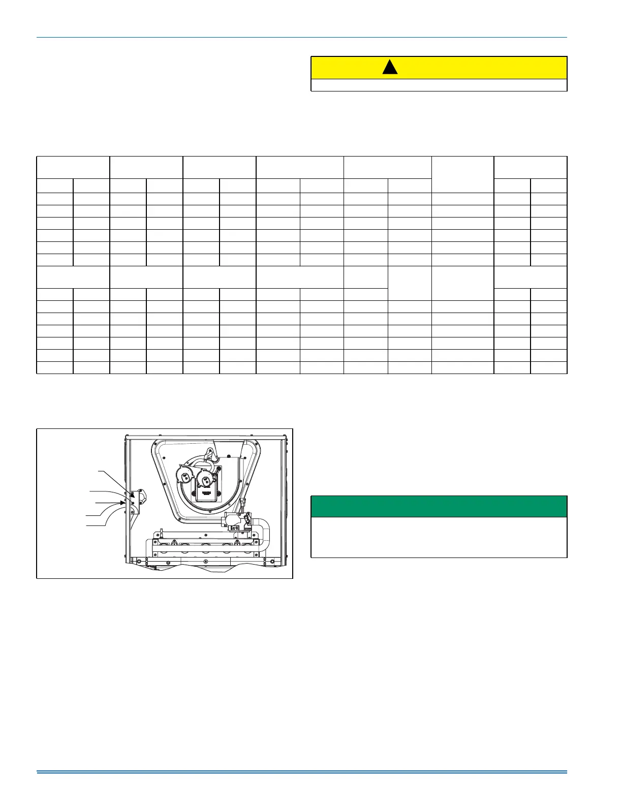
2. Remove the screws retaining the wiring box cover. Route the power
wiring through the opening in the unit into the junction box with a
conduit connector or other proper connection. In the junction box
there will be 3 wires, a Black Wire, a White Wire. Connect the
power supply as shown on the unit-wiring label on the inside of the
blower compartment door or the wiring schematic in this section.
The black furnace lead must be connected to the L1 (hot) wire from
the power supply. The white furnace screw must be connected to
neutral. Connect the power supply ground to the green screw
(equipment ground) An alternate wiring method is to use a field pro-
vided 2” (5.1 cm) x 4” (10.2 cm) box and cover on the outside of the
furnace. Route the furnace leads into the box using a protective
bushing where the wires pass through the furnace panel. After mak-
ing the wiring connections replace the wiring box cover and screws.
Refer to Figure 16.
3. The furnace's control system requires correct polarity of the power
supply and a proper ground connection. Refer to Figure 16.
CONTROL WIRING
This furnace can be connected to the wall thermostat and outdoor A/C
or heat pump using either conventional low voltage (24 VAC) thermo-
stat wiring OR using four-wire digital communications wiring. To use
conventional low voltage wiring, see the section below entitled “Con-
ventional Low Voltage Control Wiring”. To use four-wire communica-
tions control wiring, see the section below entitled “Control Wiring using
Communicating Controls”.
The Communicating System consists of several intelligent communicat-
ing components including the Communicating Thermostat Control
(touch-screen wall thermostat), modulating variable speed furnace, air
conditioner (15 and 18 SEER premium air conditioners) or heat pump
(13, 15 and 18 SEER premium heat pumps), which continually commu-
nicate with each other via a four-wire connection called the A-R-C-B.
Commands, operating conditions, and other data are passed continu-
ally between components over the A-R-C-B. See Figure 17. The result
is a new level of comfort, versatility, and simplicity.
CAUTION
Use copper conductors only.
!
Table 7: Ratings & Physical / Electrical Data
High Fire
Input
Low Fire
Input
High Fire
Output
Low Fire
Output
Nominal
Airflow
Max.
Over-current
Protect
Max. Outlet
Air Temp
MBH kW MBH kW MBH kW MBH kW CFM
m
3
/min
°F °C
60 17.6 39 11.4 47 13.8 31 9.1 1200 34.0
10
190 88
80 23.5 52 15.2 63 18.5 42 12.2 1200 34.0
10
190 88
80 23.5 52 15.2 63 18.5 42 12.2 1600 45.3
15
190 88
100 29.3 65 19.0 80 23.4 52 15.2 1600 45.3
15
190 88
100 29.3 65 19.0 80 23.4 52 15.2 2000 56.6
20
190 88
120 33.7 78 22.9 96 26.9 62 18.3 2000 56.6
20
190 88
High Fire
Air Temp. Rise
Low Fire
Air Temp. Rise
Blower Blower Size
AFUE
Total Unit
Amps
Min. wire Size
(awg) @ 75 ft
one way
Operating
weight
°F °C °F °C HP Amps In. cm % Lbs. Kg.
30-60 17-33 15-45 8-25 1/2 7.7 11 x 8 27.9 x 20.3 80.0 9.0 14 94 43
30-60 17-33 20-50 11-28 1/2 7.7 11 x 8 27.9 x 20.3 80.0 9.0 14 103 47
30-60 17-33 20-50 11-28 3/4 9.6 11 x 10 27.9 x 25.4 80.0 12.0 14 114 52
30-60 17-33 20-50 11-28 3/4 9.6 11 x 10 27.9 x 25.4 80.0 12.0 14 118 54
30-60 17-33 20-50 11-28 1 12.8 11 x 11 27.9 x 27.9 80.0 14.0 12 122 55
30-60 17-33 20-50 11-28 1 12.8 11 x 11 27.9 x 27.9 80.0 14.0 12 129 57
FIGURE 16: Electrical Wiring
Electrical Entry
Junction
Box
L1-Hot
Neutral
Connect ground
lead to screw
BLK
WHT
IMPORTANT
The power connection leads and wiring box may be relocated to the
left side of the furnace. Remove the screws and cut wire tie holding
excess wiring. Reposition on the left side of the furnace and fasten
using holes provided.
 Loading...