5402847-UIM-A-0917
14 Johnson Controls Unitary Products
CONTROL WIRING USING COMMUNICATING
CONTROLS (VARIABLE CAPACITY OUTDOOR
MODELS)
The Communicating System consists of several intelligent communicat-
ing components including the Hx
TM
Thermostat, the variable speed fur-
nace and the modulating air conditioner or heat pump. These
components continually communicate with each other via the wire con-
nections shown in Figure 20. Commands, operating conditions, and
other data are passed continually between components over the A-R-C-
B and A-C-B bus. The result is a new level of comfort, versatility, and
simplicity.
In order to use this furnace with a variable capacity outdoor unit, it must
be installed with a communicating Hx thermostat.
Use the wiring diagram in Figure 20 to connect the furnace control
and the Hx
TM
Thermostat (wall thermostat) to the communicating out-
door unit. Be sure that all of the “A+” terminals are connected together,
all of the “B-” terminals are connected together, all of the “C” terminals
are connected together and the “R” terminals from the Hx thermostat to
the indoor unit are connected together. Do NOT connect the “R” wire to
the outdoor unit. The four small screw terminals in the terminal block on
the furnace control should be used.
Connect a short piece of thermostat wire (18 gage minimum) to the
ARCB terminals on the furnace control board. Use wire connectors to
connect this wire to the room thermostat wire and the outdoor unit ther-
mostat wire. The outdoor unit contains its own control transformer. DO
NOT run a thermostat “R” wire to the outdoor unit. See Figure 20 for
details.
Float Switch Input
An optional switch may be connected to the FLT SWT terminals on the
control board. This feature is only functional when used with the Com-
municating Control. It is intended for use with a water overflow switch
that has contacts in either the normally open (NO) or (NC) position.
Auxiliary Switch Input
An optional switch may be connected to the AUX SWT terminals on the
control board. This feature is only functional when used with the Com-
munication Control. Refer to Communication Control Installation Man-
ual.
LOW VOLTAGE CONTROL WIRING CONNECTIONS
Install the field-supplied thermostat by following the instructions that
come with the thermostat. With the thermostat set in the OFF position
and the main electrical source disconnected, connect the thermostat
wiring from the wiring connections on the thermostat to the terminal
board on the ignition module, as shown in Figures 21-24. Electronic
thermostats may require the common wire to be connected. Apply
strain relief to thermostat wires passing through cabinet. If air condition-
ing equipment is installed, use thermostat wiring to connect the Y and C
terminals on the furnace control board to the proper wires on the con-
densing unit (unit outside).
The 24-volt, 40 VA transformer is sized for the furnace components
only, and should not be connected to power auxiliary devices such as
humidifiers, air cleaners, etc. The transformer may provide power for an
air conditioning unit contactor.
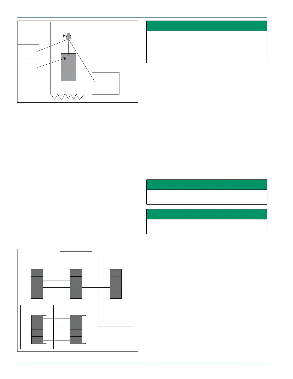
FIGURE 19: Terminal Screw Wire Connection
FIGURE 20: Furnace with Variable Capacity AC or HP
WIRE
CONNECTOR
THERMOSTAT
OUTDOOR UNIT
A+
R
C
B-
TERMINAL
SCREW
INDOOR UNIT
NOTE
ENSURE ONLYONE WIRE UNDER
TERMINAL SCREW.
TO CONNECT MORE THAN ONE WIRE:
1. CONNECT ONLY TERMINAL END OF
6” WIRE PIGTAIL.
2. USE WIRE CONNECTOR TO CONNECT
OTHER END OF PIGTAIL TO OTHER
WIRES.
A0236-001
MODULATING FURNACE
COMMUNICATING
CONTROL
)851$&(
&20081,&$7,1*
&21752/
9$5,$%/(&$3$&,7<
$&+($73803
&20081,&$7,1*
&21752/
$
+[7+(50267$7
&20081,&$7,1*
&21752/
70
,1'225
((9&21752/
IMPORTANT
Do not place more than one wire under any single communication
terminal screw (there are four communication terminal screws). If
more than one wire must be connected to a terminal screw, attach
only the terminal end of a one wire pigtail no longer than 6“, and
use a wire connector to connect the other end of the pigtail to the
other wires. Failure to do this will result in nuisance communication
error faults. See Figure 19.
IMPORTANT
Set the heat anticipator in the room thermostat to 0.4 amps. Setting it
lower will cause short cycles. Setting it higher will cause the room
temperature to exceed the set points.
IMPORTANT
Some electronic thermostats do not have adjustable heat anticipa-
tors. They should be set to six cycles per hour. Follow the thermostat
manufacturer's instructions.
 Loading...