5402847-UIM-A-0917
24 Johnson Controls Unitary Products
ADJUSTMENT OF MANIFOLD GAS PRESSURE &
INPUT RATE
Inlet and manifold gas pressure may be measured by connecting the
“U” tube manometer to the gas valve with a piece of tubing. Follow the
appropriate section in the instructions below. Refer to Figure 28 for a
drawing of the locations of the pressure ports on the gas valve.
Turn gas off at the ball valve or gas cock on gas supply line
before the gas valve. Find the pressure ports on the gas
valve marked Out P and In P.
1. The manifold pressure must be taken at the port marked OUT P.
2. The gas line pressure must be taken at the port marked IN P.
3. Using a 3/32” (2.4 mm) Allen wrench, loosen the set screw by turn-
ing it 1 turn counter clockwise. DO NOT REMOVE THE SET
SCREW FROM THE PRESSURE PORT.
Read the inlet gas pressure
Connect the positive side of the manometer to the IN P Tap on the gas
valve. Do not connect any tubing to the negative side of the manometer,
as it will reference atmospheric pressure. Refer to Figure 29 for connec-
tion details.
1. Turn gas and electrical supplies on and follow the operating instruc-
tions to place the unit back in operation.
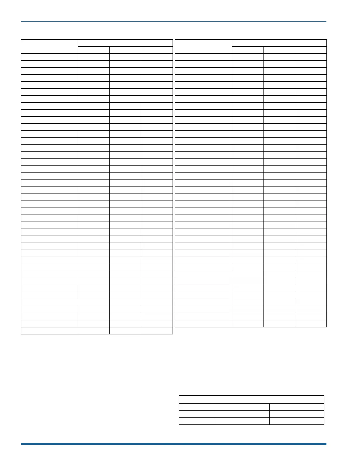
Table 11: Gas Rate (CU FT/HR)
Seconds For
1 Revolution
Size of Test Dial
Seconds For
1 Revolution
Size of Test Dial
1 Cu Ft 2 Cu Ft 5 Cu Ft 1 Cu Ft 2 Cu Ft 5 Cu Ft
10 360 720 1800 50 72 144 360
11 327 655 1636 51 71 141 355
12 300 600 1500 52 69 138 346
13 277 555 1385 53 68 136 340
14 257 514 1286 54 67 133 333
15 240 480 1200 55 65 131 327
16 225 450 1125 56 64 129 321
17 212 424 1059 57 63 126 316
18 200 400 1000 58 62 124 310
19 189 379 947 59 61 122 305
20 180 360 900 60 60 120 300
21 171 343 857 62 58 116 290
22 164 327 818 64 56 112 281
23 157 313 783 66 54 109 273
24 150 300 750 68 53 106 265
25 144 288 720 70 51 103 257
26 138 277 692 72 50 100 250
27 133 267 667 74 48 97 243
28 129 257 643 76 47 95 237
29 124 248 621 78 46 92 231
30 120 240 600 80 45 90 225
31 116 232 581 82 44 88 220
32 113 225 563 84 43 86 214
33 109 218 545 86 42 84 209
34 106 212 529 88 41 82 205
35 103 206 514 90 40 80 200
36 100 200 500 92 39 78 196
37 97 195 486 94 38 76 192
38 95 189 474 96 38 75 188
39 92 185 462 98 37 74 184
40 90 180 450 100 36 72 180
41 88 176 439 102 35 71 178
42 86 172 429 104 35 69 173
43 84 167 419 106 34 68 170
44 82 164 409 108 33 67 167
45 80 160 400 110 33 65 164
46 78 157 391 112 32 64 161
47 76 153 383 116 31 62 155
48 75 150 375 120 30 60 150
49 73 147 367
Table 12: Inlet Gas Pressure Range
INLET GAS PRESSURE RANGE
Natural Gas Propane (LP)
Minimum* 4.5” W.C. (1.12 kPa) 8.0” W.C. (1.99 kPa)
Maximum 10.5” W.C. (2.61 kPa) 13.0” (3.24 kPa) W.C.
 Loading...