Unitary Products Group 23
246681-YTG-B-0607
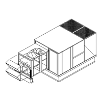
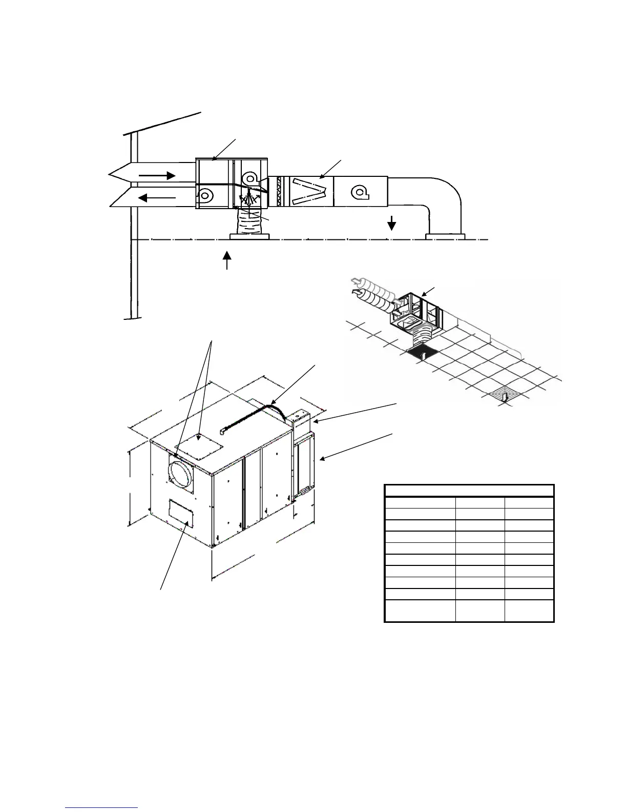
FIGURE 11 - HORIZONTAL SPLIT SYSTEM UERV’S FOR VH006 AND VH011 SERIES
Model
CFM Range 300-550 600-1,000
A 34.70 40.25
B 24.75 30.25
C 24.62 32.50
D 5.63 10.00
E 40.33 50.25
Intake Duct 9 rd 10 rd
Exhaust Duct 9 rd 10 rd
Return Duct
(bottom of UERV)
16 or 18
oval
16 or 18
oval
1. Fresh air intake can be field located on top or end of unit.
2. Electrical control box can be located to either side for access.
Dimensions
4. Static test ports are provided for verification of CFM.
5. Filter rack accepts 1" or 2" filters and comes with flex connector to air handler.
Features
3. Access panels located on both sides of ERV for servicing.
Note: Applications with extensive duct on intake and exhaust may require booster fans for airflow.
H06 and H11 Series
Control Box
(moveable to either
side)
Filter Rack
(1or2inch)
Air Handler
Balancing Damper
UERV
ERV
VH006
VH011
6. On Horizontal and upflow UERVs, the transformer is supplied for field installation.
A
B
C
E
Air Handler End
Exhaust Air
(Transition
Provided)
Intake Air
(field selected)
D
 Loading...