193
JOHNSON CONTROLS
SECTION 8 – UNIT OPERATION
FORM 150.67-NM1
ISSUE DATE: 4/28/2017
8
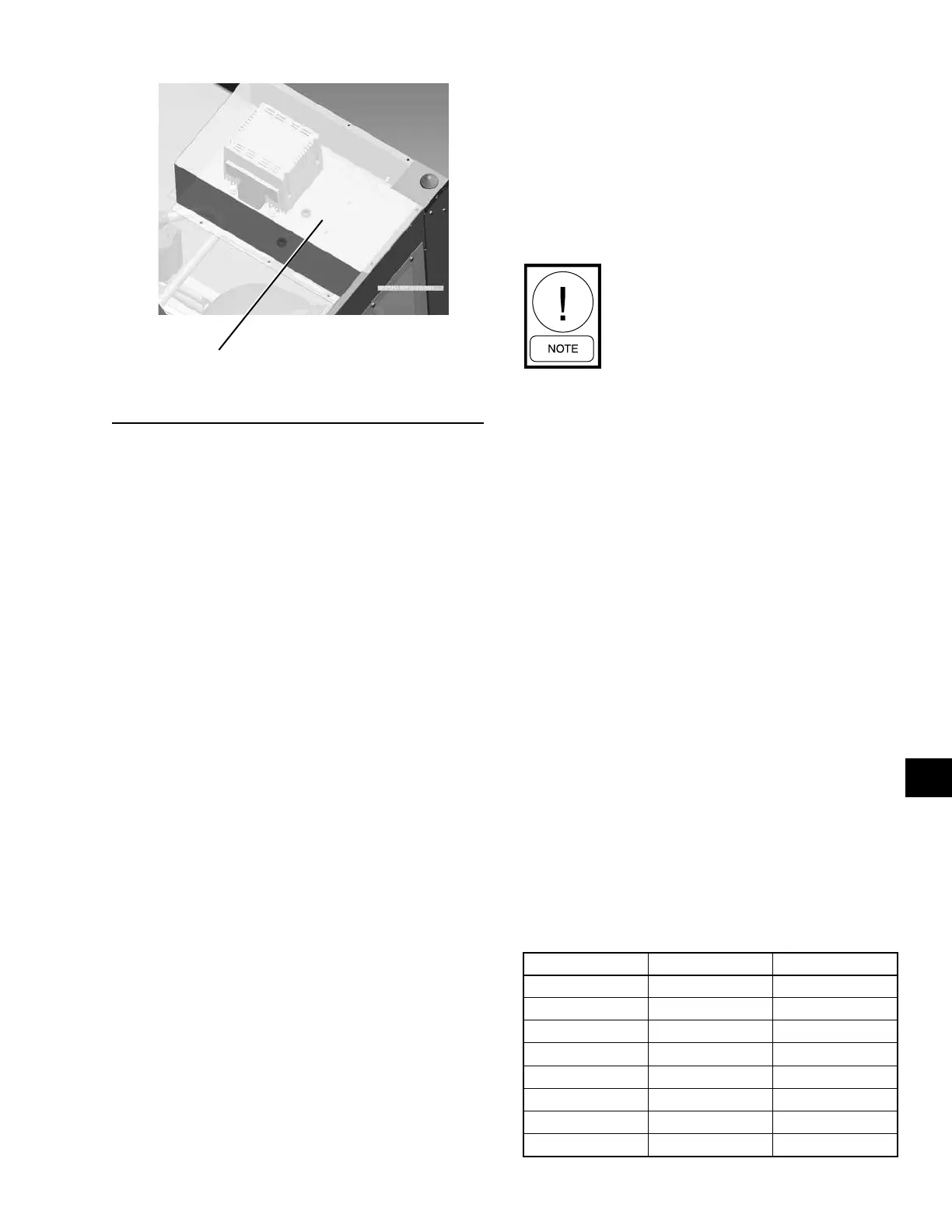
VFD Enclosure
LD12081
FIGURE 50 - TYPICAL VFD ENCLOSURE
CONFIGURATIONS
The VFD will control fan speed when only a single fan
is running on a system. As discharge pressure rises and
falls, the fan speed will be increased from zero RPM to
full speed. As discharge pressure continues to rise, the
VFD will operate the fan at full speed and the second
fan will be brought on in a system, if needed. Whenev-
er the second fan is brought on, the inverter will already
be running the first fan at full speed. When discharge
pressure falls, the chiller microprocessor will turn the
second fan OFF by de-energizing the fan contactor.
If pressure continues to fall, VFD speed will decrease
in an effort to maintain discharge pressure. Speed may
drop to the point where the VFD turns the fan com-
pletely OFF or virtually OFF with a continued drop in
pressure.
The VFD control input signal is from the discharge
pressure transducer in the respective system. The trans-
ducer signal feeds both the chiller microprocessor
board and the VFD. The VFD controls the fan speed
based on discharge pressure.
The VFD will control the fan speed not only in low am-
bient conditions, but in all ambients based on discharge
pressure. Speed control of the respective system will
occur whenever high voltage power is applied to the
VFD power inputs through the 7M contactor. The
chiller microprocessor will energize the 7M and 10M
contactors whenever the system liquid line solenoid is
energized.
The VFD controls the speed of the fan based on a
discharge pressure setpoint and a differential control
range. When a compressor starts in a system, the in-
verter is activated through the 7M contactor, which
is controlled from the respective liquid line solenoid
valve control signal. At discharge pressures below 260
PSIG, the VFD will turn the fan OFF or speed will be
reduced to all but small movements in fan rotation.
The pressures indicated in this section
describing the VFD control will vary
from VFD to VFD. Expect tolerances
for the entire pressure range of con-
trol to potentially shift -0 PSIG/+24
PSIG.
The VFD will ramp up the speed of the fan as pres-
sure rises above the low end of the speed control range.
Throughout the pressure control range, the VFD con-
trols the speed of the fan based on a discharge pressure
in the range of approximately 260 to 292 PSIG. At
pressures above 292 PSIG, the VFD will run the sys-
tem fan at full speed.
As pressure drops below 292 PSIG, the VFD will slow
the speed of the fan to try to maintain discharge pres-
sure within the control range. The VFD will try to
maintain pressure in the range of 260 to 292 PSIG by
raising and lowering the speed of the fan. If pressure
drops below 260 PSIG, the VFD will virtually turn the
system fan completely OFF. Some slight fan move-
ment or very slow rotation may be noted, although the
fan may appear to stop completely.
CONFIGURATION (JUMPERS AND
POTENTIOMETERS)
Each VFD is pre-configured at the factory prior to
shipping and should be ready for operation when it ar-
rives onsite. A quick check of the settings is recom-
mended. The jumpers must be in the positions shown
in Table 25.
TABLE 25 - VFD JUMPERS
JUMPER 60 HZ 50 HZ
J2 REMOVE —
J3 IN —
J4 REMOVE —
J5 IN —
J6 IN —
J7 IN —
J8 IN —
J9 IN REMOVE
 Loading...


