197
JOHNSON CONTROLS
SECTION 8 – UNIT OPERATION
FORM 150.67-NM1
ISSUE DATE: 4/28/2017
8
As pressure drops below 292 PSIG, the VFD will slow
the speed of the fan to try to maintain discharge pres-
sure within the control range. The VFD will try to
maintain pressure in the range of 260 to 292 PSIG by
raising and lowering the speed of the fan. If pressure
drops below 260 PSIG, the VFD will virtually turn the
system fan completely OFF. Some slight fan move-
ment or very slow rotation may be noted, although the
fan may appear to stop completely.
CONFIGURATION (JUMPERS AND
POTENTIOMETERS)
Each VFD is pre-configured at the factory prior to
shipping and should be ready for operation when it ar-
rives onsite. A quick check of the settings is recom-
mended. The jumpers must be in the positions shown
in Table 27.
TABLE 27 - VFD JUMPERS
JUMPER 60 HZ 50 HZ
J2 REMOVE —
J3 IN —
J4 REMOVE —
J5 IN —
J6 IN —
J7 IN —
J8 IN —
J9 IN REMOVE
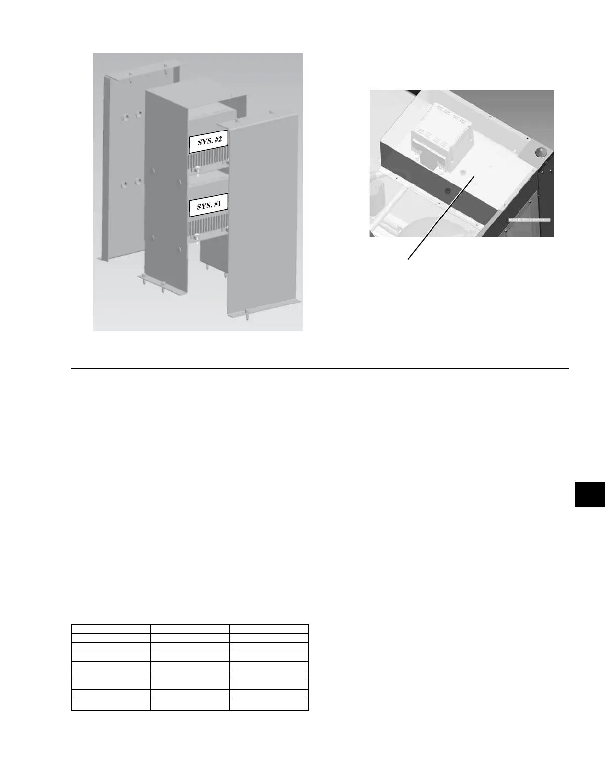
FIGURE 55 - TYPICAL VFD ENCLOSURE CONFIGURATIONS
Dual System VFD Enclosure
SYS. #2
SYS. #1
Single System VFD Enclosure
LD12081
LD11299a
Potentiometer settings are also preset at the factory.
The potentiometers should be in the positions shown in
Figure 57. The pots do not have numerical settings and
are set according to the arrow positions indicated. DO
NOT change the potentiometer settings unless they do
not match the positioning of the potentiometers shown
in Figure 57. The position of the potentiometers are as
follows:
• P1 should be full CW (260 PSIG)
• P2 should be full CCW (32 PSIG).
Modifying these settings may cause damage to the
chiller or control problems.
The P1 pot sets the setpoint which is the top end of the
control range. This setting is the discharge pressure at
which the fan will be operating at full speed. The P2
pot sets the range. This is the range of pressure where
the VSD modulates the fan speed from 0 RPM to full
speed. The range is subtracted from the setpoint to cal-
culate the 0 RPM pressure.
Wiring
VFD wiring is simple and requires only 3-phase power
in, 3-phase power out, and a 2-wire signal from the
transducer. No start, stop, or other alternate power re-
 Loading...


