41
JOHNSON CONTROLS
SECTION 4 – INSTALLATION
FORM 150.67-NM1
ISSUE DATE: 4/28/2017
4
size of the pipe in which it is to be installed (see
manufacturer’s instructions furnished with the
switch). The switch is to be wired to terminals 13
and 14 of CTB1 located in the control panel, as
shown on the unit wiring diagram.
The ow switch MUST NOT be used
to start and stop the chiller (i.e. start-
ing and stopping the chilled water
pump). It is intended only as a safety
switch.
PIPEWORK ARRANGEMENT
The following are suggested pipework arrangements
for single unit installations, for multiple unit installa-
tions, each unit should be piped as shown.
Recommendations of the Building Services
Research Association.
DUCT WORK CONNECTION
General Requirements
The following duct work recommendations are intend-
ed to ensure satisfactory operation of the unit. Failure
to follow these recommendations could cause damage
to the unit, or loss of performance, and may invalidate
the warranty.
When ducting is to be fitted to the fan discharge it is
recommended that the duct should be the same cross-
sectional area as the fan outlet and straight for at least
three feet (1 meter) to obtain static regain from the fan.
Duct work should be suspended with flexible hang-
ers to prevent noise and vibration being transmitted to
the structure. A flexible joint is also recommended be-
tween the duct attached to the fan and the next section
for the same reason. Flexible connectors should not be
allowed to concertina.
The unit(s) is not designed to take structural loading.
No significant amount of weight should be allowed to
rest on the fan outlet flange, deck assemblies or con-
denser coil module. No more than 3 feet (1 meter) of
light construction duct work should be supported by
the unit. Where cross winds may occur, any duct work
must be supported to prevent side loading on the unit.
If the ducts from two or more fans are to be combined
into a common duct, back-flow dampers should be fit-
ted in the individual fan ducts. This will prevent re-
circulation of air when only one of the fans is running.
Units are supplied with outlet guards for safety and to
prevent damage to the fan blades. If these guards are
removed to fit duct work, adequate alternative precau-
tions must be taken to ensure persons cannot be harmed
or put at risk from rotating fan blades.
WIRING
Liquid Chillers are shipped with all factory-mounted
controls wired for operation.
Field Wiring
Power wiring must be provided through a fused discon-
nect switch to the unit terminals (or optional molded dis-
connect switch) in accordance with N.E.C. or local code
requirements. Minimum circuit ampacity and maximum
dual element fuse size are given in Table 7.
Copper power wiring only should be used for supply-
ing power to the chiller. This is recommended to avoid
safety and reliability issues resulting from connection
failure at the power connections to the chiller. Alumi-
num wiring is not recommended due to thermal char-
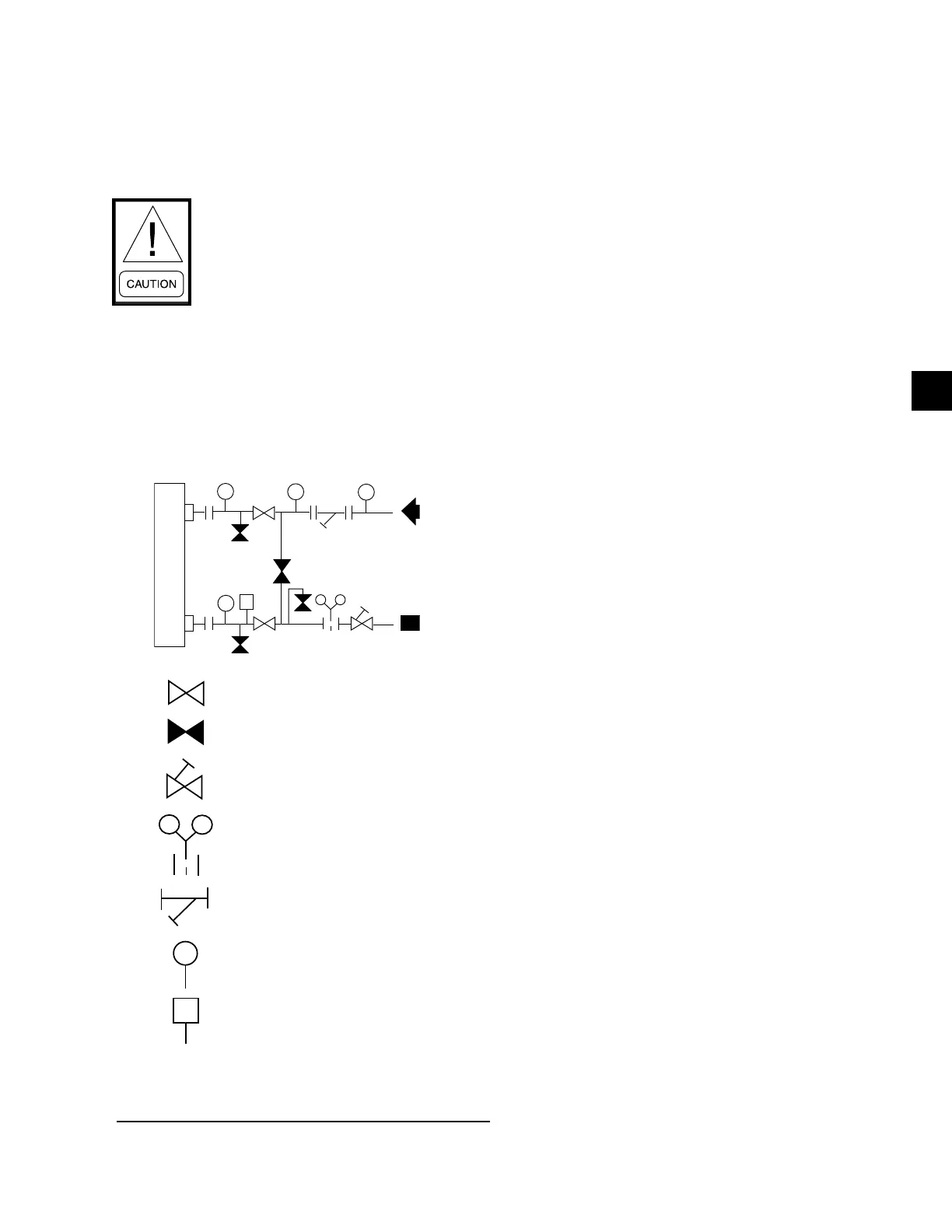
FIGURE 9 - CHILLED LIQUID SYSTEM
LD06597A
ISOLATING VALVE - NORMALLY OPEN
ISOLATING VALVE - NORMALLY CLOSED
FLOW REGULATING VALVE
FLOW MEASUREMENT DEVICE
STRAINER
PRESSURE TAPPING
FLOW SWITCH
LD06596
 Loading...


