JOHNSON CONTROLS
198
FORM 150.67-NM1
ISSUE DATE: 4/28/2017
SECTION 8 – UNIT OPERATION
quirements are needed to run the VFD. Figure’s 56 and
57 show the power and control wiring schematically
as well as the actual connections. The VFD controlled
fan will operate whenever the liquid line solenoid on
the respective system is energized.
PROGRAMMING
Condenser fan control type must be programmed un-
der both the OPTIONS and PROGRAM keys when a
VFD is installed on the chiller. Under the OPTIONS
key, FAN CONTROL must be programmed for DIS-
CHARGE PRESSURE CONTROL only. This will as-
sure condenser fan control of the chiller is solely by
discharge pressure, with no ambient control.
Under the PROGRAM key, the FAN
CONTROL ON PRESSURE should
be programmed for 425 PSIG and the
FAN DIFFERENTIAL OFF PRES-
SURE must be programmed for 125
PSIG.
Programming as suggested assures the chiller control
points for the second fan in the fan staging sequence
and the inverter control points are matched for opti-
150A L1 T1 150
151A L2 T2 151
152A L3 T3 152
CONDENSER
FAN NO. 1
SPEED
CONTR.
7M
250A L1 T1 250
251A L2 T2 251
252A L3 T3 252
CONDENSER
FAN NO. 2
SPEED
CONTR.
10M
LD11301
FIGURE 56 - INVERTER POWER WIRING SC
mum control of the fans at reduced ambient tempera-
tures. When the chiller and VFD fan control points are
programmed properly, the fans will operate as outlined
in Table 28.
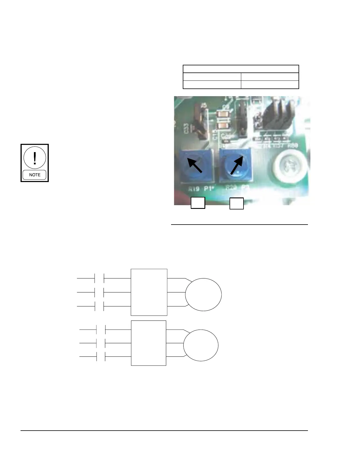
POTENTIOMETER SETTINGS
P1 P2
292 PSI 32 PSI
FIGURE 57 - POTENTIOMETER SETTINGS
LD11300a
 Loading...


