303
JOHNSON CONTROLS
FORM 201.21-NM1 (1223)
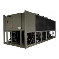
PRINTER WIRING
A “serial” printer may be connected to the TB1 connec-
tor on the Chiller Logic Board for the purposes of log-
ging data and troubleshooting. Weightronix Imp-2600,
Seiko DPU-414, and Okidata Microline 184 printers or
equivalents may be used.
Printer designs change rapidly. The
user should use the printer manual
for the respective printer for set-up
and wiring.
Data from the chiller is transmitted at 1200 baud. Wir-
ing diagrams for cables are shown below:
OKIDATA MICROLINE 184
25 pin RS-232 (DB-25P)
25 pin RS-232 (DB-25P)
TB1 Chiller Control Board
11
CTS
RD
GND
DSR
RS-232
TXD
GND
TB1-2
TB1-3
TB1-5
3
7
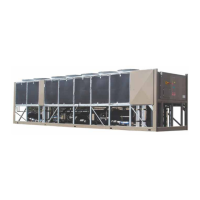
SEIKO DPU-414
9 pin RS-232 (DB-9) TB1 Chiller Control Board
8
CTS
RD
GND
DSR
TXD
GND
TB1-2
TB1-3
TB1-5
3
5
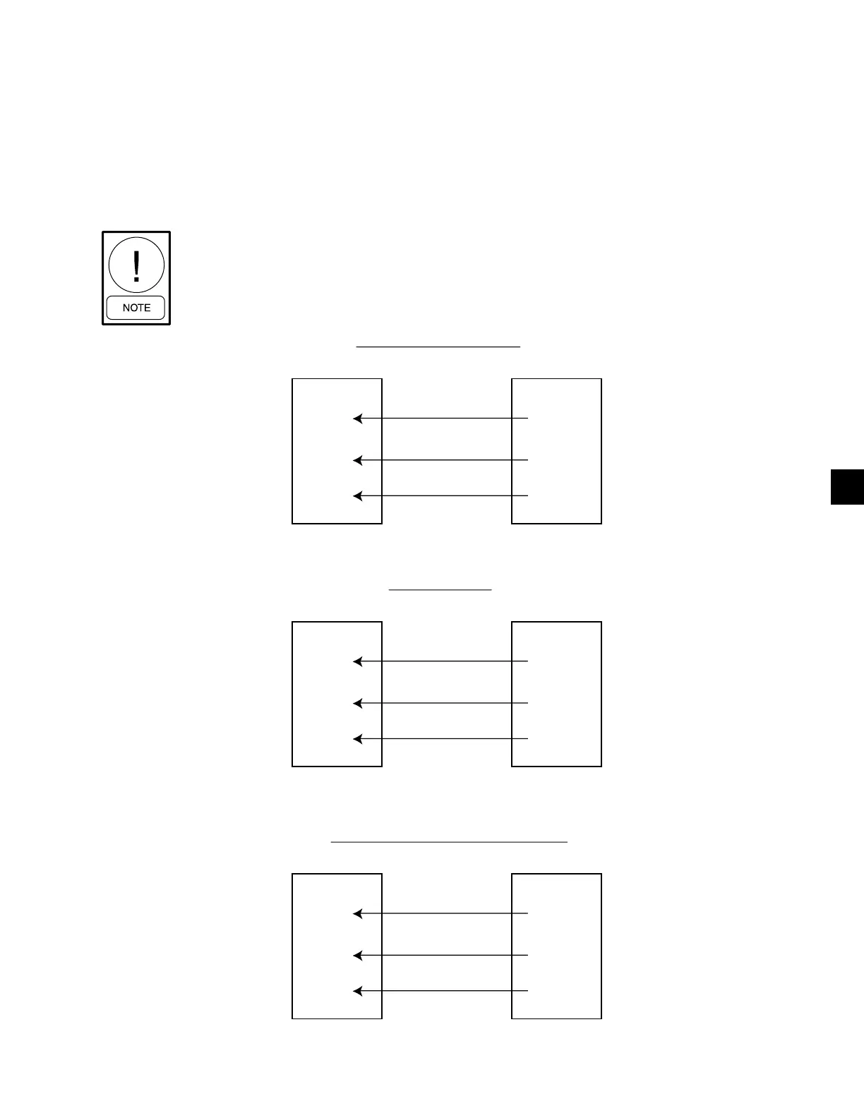
WEIGHTRONIX IMP-24, MODEL 2600
TB1 Chiller Control Board
5
CTS
RD
GND
DSR
TXD
GND
TB1-2
TB1-3
TB1-5
2
7
FIG. 37 - PRINT CABLE - CHILLER TO SERIAL PRINTER
99
 Loading...