Pressure sensors (B3 and B4)
One for each cooling circuit, and connected to the coil sumps.
These provide information to the system for fan speed control
in the summer and winter cycles, management of defrosts on
heat pumps, and system high pressure prevent and lockout
functions.
NTC probes (B5 and B6)
B5 - Detect and control entering water temperature (cool only
and heat pump units).
B6 - Detect and control leaving water temperature.
These probes provide all information necessary for antifreeze
protection and control of antifreeze and backup heaters. If
necessary, they enable controlling the temperature of the
water leaving the exchanger.
Commissioning
The Start screen appears about 45 seconds after connecting
the power supply. Default language: English.
1st screen. Start (water temperature/unit status)
- Entering water temperature.
- Leaving water temperature.
- Unit status (ON/OFF).
Press “Down” to access the second screen.
2nd screen. Selection of status and operating mode
Selection of ON/OFF status (Enter, Up and Down keys).
On heat pump units, select the Cool/Heat operating mode
(by means of "Enter", "Up" and "Down").
To go back to the 1st screen, press Esc.
System configuration (for authorized servicing personnel
only)
3rd screen. Insert password
The 3rd screen, Insert password, is accessed by pressing
“Up” on screen 1 (Start), or “Down” on screen 2 (Selection
of status/operating mode).
- From the Insert password screen, press Enter.
- Enter the password by means of the Up key.
- Press Enter to access the 4th screen, Menu.
4th screen. Menu
This screen gives access to an range of submenus that allow
obtaining information concerning the unit or setting the oper-
ating parameters of same. These submenus are as follows:
-/- Probe configuration
-A- Antifreeze
-B- Input/output
-c- Compressor configuration
-d- Defrost
-F- Condensation (fans)
-H- Unit configuration
-P- Alarm settings
-r- Temperature (param.) control
-Fr- Software version/language selection
-t- Time configuration (not available)
To enter a submenu, press the Up or Down key to select,
and then Enter.
Once the desired parameters have been changed by press-
ing the Enter, Up and Down keys, press Prg to confirm these
modifications and go back to the Menu screen.
To exit the Menu screen, press Esc.
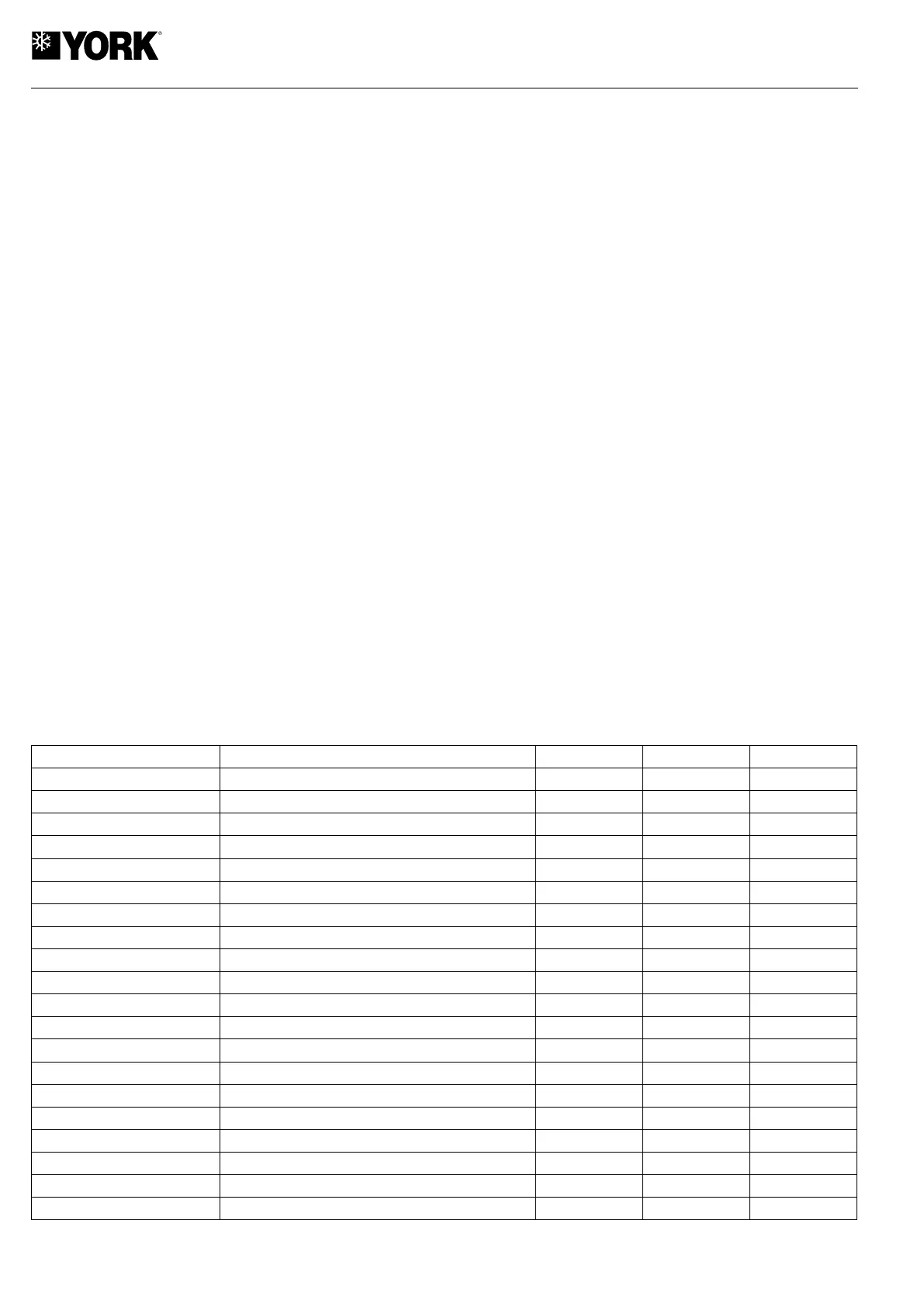
-/- Configuration of the probes
DESCRIPTION RANGE UNIT. VALUE
Probe B3 calib. Coil pressure, circuit 1
-9.9 / 9.9 bar 0
Probe B4 calib. Coil pressure, circuit 2 -9.9 / 9.9 bar 0
Probe B5 calib. Entering water temp., exchanger -9.9 / 9.9 °K 0
Probe B6 calib. Leaving water temp, exchanger -9.9 / 9.9 °K 0
Probe B7 calib. Outdoor temp. -9.9 / 9.9 °K 0
Probe B8 calib. Dynamic set point -9.9 / 9.9 % 0
Probe B1 enable Y/N - N
Probe B2 enable Y/N - N
Probe B3 enable Coil pressure, circuit 1 Y/N - Y
Probe B4 enable Coil pressure, circuit 2 Y/N
-
Y
Probe B5 enable Entering water temp., exchanger Y/N - Y
Probe B6 enable Leaving water temp., exchanger Y/N - Y
Probe B7 enable Y/N - N
Probe B8 enable Y/N - N
Probe B9 enable Y/N - N
Probe B10 enable Y/N
-
N
Probe B3 config. Minimum value -30/150 bar 1
Probe B3 config. Maximum value -30/150 bar 46
Probe B4 config. Minimum value -30/150 bar 1
Probe B4 config. Maximum value -30/150 bar 46
 Loading...