SECTION 5 - SERVICE
JOHNSON CONTROLS
207
FORM 160.87-OM1
ISSUE DATE: 8/24/2018
5
KEYPAD INTERFACE
The keypad is read via J18. The keypad is a matrix
of conductors arranged in rows and columns (Refer to
Form 160.54-M1). There are 4 rows and 8 columns.
When a key is pressed, the conductors are pressed to-
gether at that point, creating continuity between the
row conductor and the column conductor. The keypad
is read by applying a logic low to a row while leaving
+5VDC pull-up on all other rows. The microprocessor
then reads the 8 columns. If any column has a logic low
on it, the key corresponding to that coordinate (row,
column) is being pressed. The microprocessor reads
the entire keypad by repeating this routine beginning
with row 1 and ending with row 4. The entire keypad is
continually read while the Control Center is powered.
CM-2 BOARD OR STYLE A SOLID STATE
STARTER INTERFACE
The microboard retrieves certain operating parameters
(via J10) from the compressor motor starter control
board (CM-2 Current Board for Electro-Mechanical
Starter or Style A Solid State Starter Logic Board). Re-
fer to Form 160.54-M1 for a detailed explanation of
each board. Both boards contain an 8 channel multi-
plexer. The microprocessor sequentially and continu-
ally reads channels 0 through 7. It reads each channel
by applying a 3-bit binary address to the multiplexer.
A 0 to 5VDC analog value is re-turned from each chan-
nel. The function of each is in the Table 12 on Page
207.
The microprocessor determines which board, and
therefore which starter is present, by the value returned
from channel 0. Since channels 0 through 6 are ground-
ed, the CM-2 board returns a 0VDC value. The Solid
State Starter Logic Board returns a value greater than
0.41VDC to +5VDC. If the value is less than 0.4VDC,
it indicates the starter is an Electro-mechanical (EM)
starter and the microprocessor then reads channel 7 to
retrieve the peak motor current value. A value greater
than 0.4VDC indicates the starter is an A style Solid
State Starter and the microprocessor reads channels 1
through 7.
In the Solid State Starter, channel 0 indicates the
starter size (model) and voltmeter range (300VAC or
600VAC). Channel 1 is a hardware generated 100%
FLA (prevents pre-rotation vanes from further open-
ing) or 104% FLA (closes pre-rotation vanes until mo-
tor current is less than 102%) current limit override
command that overrides normal Pro-rotation Vanes
control. Channels 2 through 4 are analog voltages that
represent phase A, B and C motor current. The highest
phase is Channels 5 through 7 are analog voltages that
represent phase A, B and C Line Voltage. The data for
each channel is shown on the below.
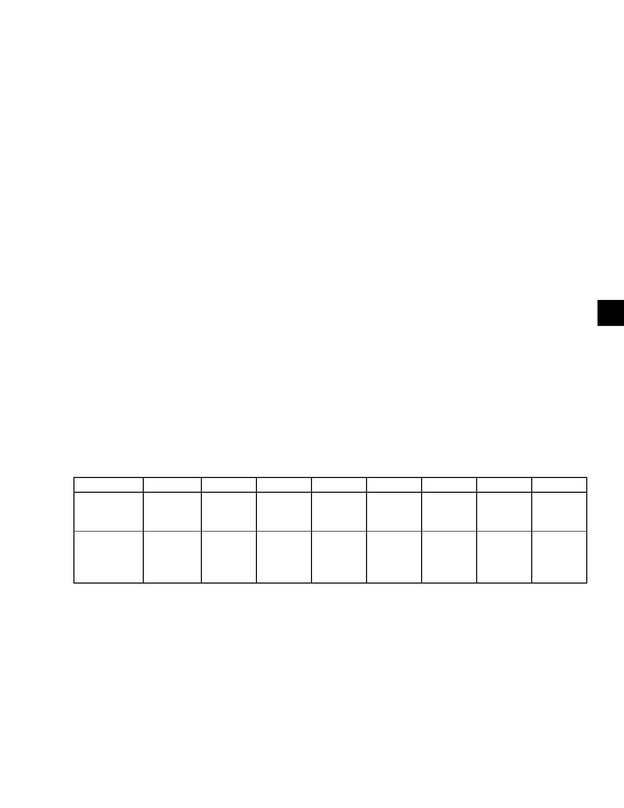
TABLE 12 - MULTIPLEXER CHANNELS
0 1 2 3 4 5 6 7
CM-2 GND GND GND GND GND GND GND
Peak Motor
Current
(%FLA)
STYLE A
SOLID STATE
STARTER
Starter
model/
voltmeter
range
Current
limit
command
Phase C
motor
current
Phase B
motor
current
Phase A
motor
current
Phase A
line
voltage
Phase B
line
voltage
Phase C
line
voltage
 Loading...