JOHNSON CONTROLS
177
SECTION 8 – UNIT OPERATION
FORM 150.72-ICOM6
ISSUE DATE: 08/03/2022
8
TABLE 24 - SAMPLE COMPRESSOR STAGING FOR RETURN WATER CONTROL
4 COMPRESSOR
COOLING SETPOINT = 45 °F (7.2 °C) RANGE = 10 °F (5.6 °C)
# OF COMP ON 0 * 1+HG 1 2 3 4
RWT
45°F
(7.2°C)
46.25°F
(7.9°C)
47.5°F
(8.6°C)
50.0°F
(10.0°C)
52.5°F
(11.4°C)
55.0°F
(12.8°C)
*Unloading only
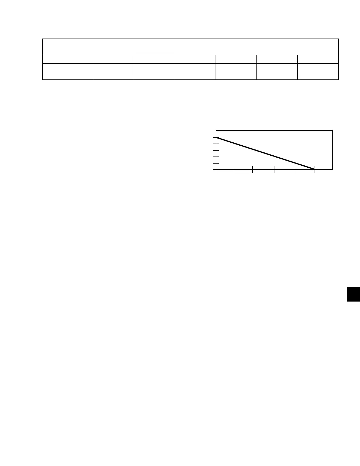
0 1 2 3 4 5
LAST RUN TIME OF LEAD SYSTEM (MINUTES)
ADJUST (DEG. F)
6
5
4
3
2
1
0
FIGURE 47 - SETPOINT ADJUST
LD11415
LEAVING CHILLED LIQUID CONTROL
OVERRIDE TO REDUCE CYCLING
To avoid compressor cycling the microprocessor ad-
justs the setpoint upward temporarily. The last run time
of the system is saved. If the last run time was greater
than 5 minutes, do not take any action. If the last run
time for the lead system was less than 5 minutes, the
microprocessor increases the setpoint high limit ac-
cording to the chart at right, with a maximum value
allowed of 50°F. See Figure 47.
If adding the setpoint adjust value to the setpoint high
limit causes the setpoint high limit to be greater than
50°F, the setpoint high limit is set to 50°F and the dif-
ference is added to the setpoint low limit.
When a system runs for greater than 5 minutes, the set-
point adjust sets back to 0. This occurs while the sys-
tem is still running.
 Loading...
