FORM 150.68-EG1 (0212)
19JOHNSON CONTROLS
Technical Data
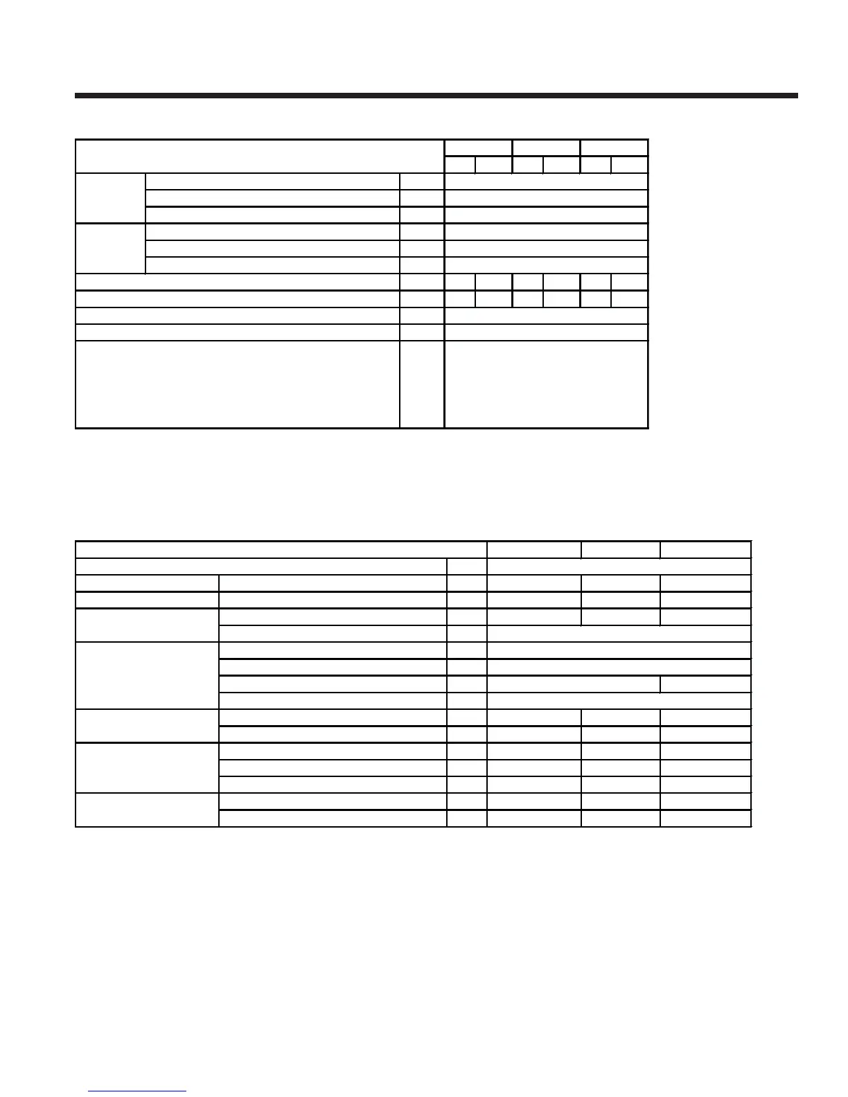
OPERATING LIMTATIONS
PHYSICAL DATA
Min. Max. Min. Max. Min. Max.
Liquid Outlet Temperature (Water) °F
Liquid Outlet Temperature Range (T)
°F
Air Temperature - Standard Unit °F
Liquid Outlet Temperature (Water) °F
Liquid Outlet Temperature Range (T)
°F
Air Temperature - Standard Unit °F
gpm
181 700 181 700 200 850
ftH
2
O
5.4 43.0 5.4 43.0 3.4 55.4
psi
psi
V
(1) Unit may operate unloaded up to 125ºFdepending on model size and site conditions.
(2) Tolerance +/-10%
Maximum Refrigerant Side Pressure
Maximum Water Side Pressure
Heat Exchanger Presssure Drop
200V 3Ø, 60Hz (nominal)
230V 3Ø, 60Hz (nominal)
380V 3Ø, 60Hz (nominal)
460V 3Ø, 60Hz (nominal)
575V 3Ø, 60Hz (nominal)
0115SE 0145SE 0170SE
Number of refrigerant circuits
Refrigerant Charge
(1)
System 1 / System 2 lb 130 / 137 181 / 132 181 / 181
Oil Charge System 1 / System 2 lb 24.2 / 24.2 37.4 / 24.2 37.4 / 37.4
Number of compressors 2 / 2 3 / 2 3 / 3
Type
Number
Type
Water Volume l 600
Water Connections inch
Number of Fans (circuit 1 / circuit 2) 4 / 4 6 / 4 6 / 6
Total Air Flow - Standard Models
Length inch 194.4 230.5 274.4
Width inch 88.4 88.4 88.4
Height inch 94.1 94.1 94.1
Shipping Weight lb 9811 11243 12124
Operating Weight lb 10472 11904 13447
(1) Liquid sub-cooling measured at the liquid line should be between 47.3 and 52.0°F at circuit full load.
Sub-cooling is determined by the level of refrigerant charge in each system
Refrigerant to Liquid
Heat Exchanger
 Loading...