87JOHNSON CONTROLS
FORM NO.: 6U6K-B01E-NB-EN
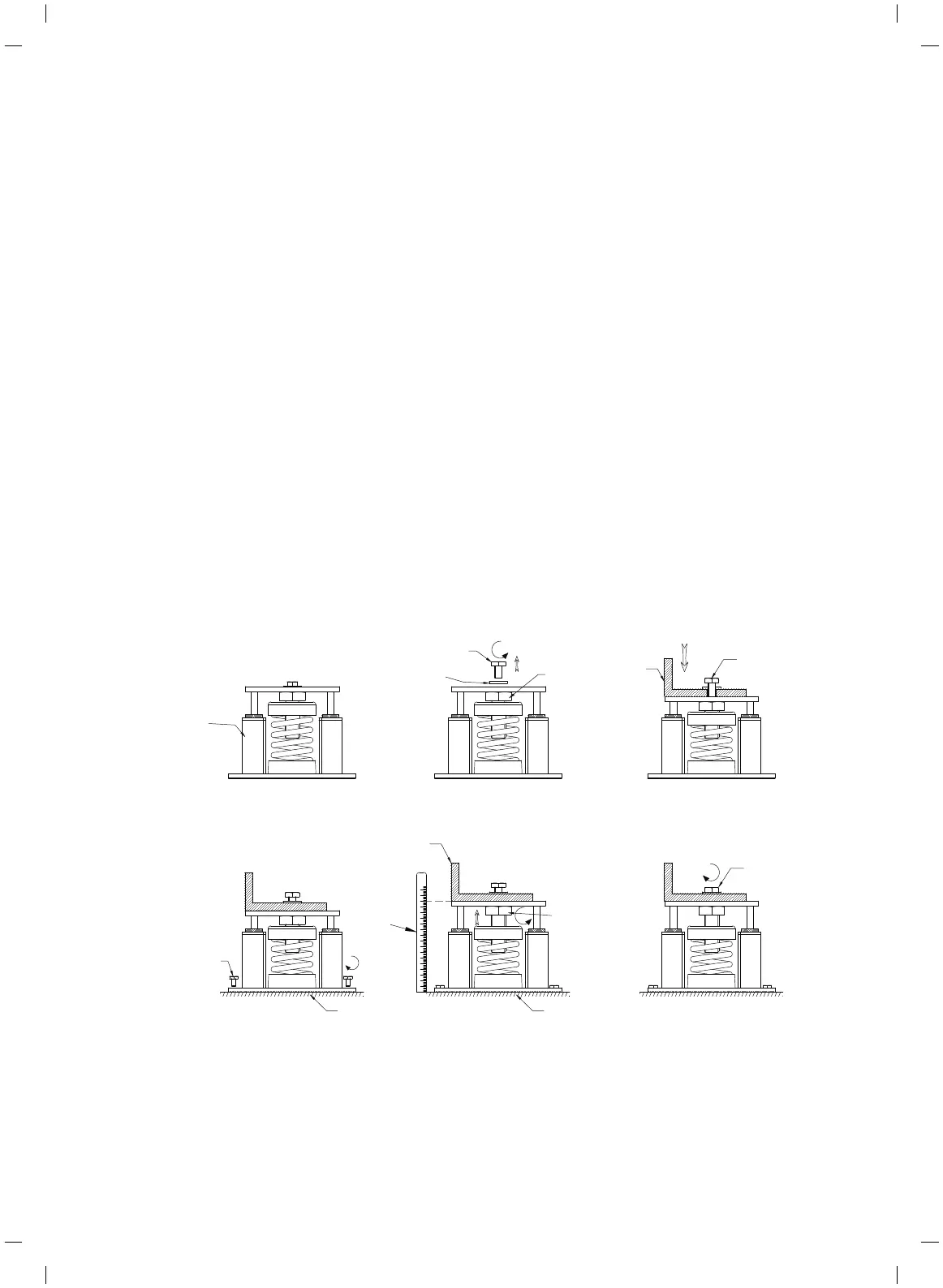
TWO INCH DEFLECTION SPRING ISOLATOR INSTALLATION
AND ADJUSTMENT
Installation Instructions
1.Read instructions in their entirety before beginning
installation.
2.Isolators are shipped fully assembled. Make sure the AVM
types are correct (print codes and adhesive labels) and match
each load point with corresponding isolators.
3.Twist off the xing bolt and washer anticlockwise.
4.Set isolators on oor. Ensure that all isolator centerlines match
the equipment mounting holes. The isolator base be installed on
a level surface. Leveling all isolator bases to the same elevation
(1/4-inch maximum difference can be tolerated).
5.Place equipment on top of isolators making sure that mounting
holes of the equipment line up with isolator installation holes.
6.Place the xing bolt and washer but do not tighten them.
7.Ensure the verticality of the isolators and use bolts to x the
bases of the isolators to the level oor. Use the same torque to
fasten the bolts.
8.The adjustment process can only begin after the equipment or
machine is at its full operating weight.
9.Measure the height of the housing. Adjust each isolator in
sequence by turning adjusting bolt. Repeat this procedure on all
isolators, one at a time.
10.Fine adjust isolators to level equipment. Fasten the nut and
xing bolt.
11.Installation is complete.
Load label
Adjusting
bolt
Fixing bolt
Washer
Level basement
Adjusting
bolt
Unit
550 550 550
Unit
Fixing
bolt
550
Level basement
550 550
Fixing
bolt
Lock
Bolt
Ruler
Step 1
Step 2
Step 4
Step 5
Step 3
Step 6
SECTION 5 – TECHNICAL DATA
Cooke Industries - Phone: +64 9 579 2185 Email: sales@cookeindustries.co.nz Web: www.cookeindustries.co.nz
 Loading...