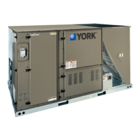
Do you have a question about the York ZJ078 and is the answer not in the manual?
| Brand | York |
|---|---|
| Model | ZJ078 |
| Category | Air Conditioner |
| Language | English |
Explains the meaning of safety signal words used in the manual.
Warning about improper installation causing injury or property damage.
Caution about R-410A refrigerant and system requirements.
Warning about fire or explosion hazard if manual is not followed.
Caution about product installation compliance with codes.
Procedure for inspecting the unit for damage during transit.
Lists related documents, parts, and unit certifications.
General safety instructions for installing the unit.
Steps to take before the main installation begins.
Specifies installation requirements and applicable codes.
Guidelines for selecting a suitable installation location for the unit.
Required clearances for unit operation, servicing, and construction.
Details the physical dimensions of the unit models in a table.
Specifies required clearances for unit operation and servicing.
Illustrates the locations of electrical entry points on the unit.
Shows the location and dimensions of side duct openings.
Details the dimensions of side duct openings for various models.
Shows the location and dimensions of the left duct opening.
Provides diagrams and dimensions for standard roof curbs.
Provides diagrams and dimensions for transition roof curbs.
Instructions on handling and reusing duct covers.
Information on saving and using side panels for economizer hoods.
Information about the scroll compressors and their oil.
Details about the unit filters and their maintenance.
Information on factory-installed electric heaters.
Details on gas-fired heaters and their features.
Table for sizing gas pipes based on length and capacity.
Table showing minimum supply air requirements for gas heat.
Limitations and installation notes for duct smoke detectors.
Information on factory or field installed motorized outdoor dampers.
Details on factory or field installed economizer options.
Information on factory or field installed power exhaust options.
Information on hood components and their packaging.
Explanation of VAV option and its function.
Details about the duct static pressure transducer used in VAV systems.
Information on the factory-installed Variable Frequency Drive.
Explains the manual bypass switch for VFD units.
Details on VFD options compatible with BAS integration.
Information on the optional hot gas bypass system.
Describes how the economizer sequences function.
Details the economizer minimum position setting.
Details the operation of dual enthalpy economizer control.
Explains the auto mode for free cooling changeover control.
Describes how free cooling operates based on thermostat and sensor inputs.
How the thermostat interacts with free cooling mode.
How sensors are used in free cooling operation.
Explanation of indoor air quality sensor inputs and operation.
Instructions for checking and correcting motor phasing.
Specifications for indoor blower motors and sheaves.
Specifications for power exhaust units.
Procedures for balancing airflow in the unit.
Methods for measuring and adjusting air quantity.
Table showing additional static resistance values for components.
General overview of unit operation modes.
How to set the unit for continuous blower operation.
How the blower operates in intermittent mode.
Operation sequence for economizer with single enthalpy sensor.
Operation sequence for economizer with dual enthalpy sensors.
How power exhaust integrates with economizer operation.
Operation of motorized outdoor air dampers.
Details common cooling system errors and their handling.
Covers pressure limits, evaporator limits, ambient cooling, and compressor protection.
Describes the sequence of operations for electric heating.
Explains errors related to electric heat operation.
How the temperature limit switch affects electric heat operation.
Safety controls monitored by the UCB for electric heat.
Location and function of the limit switch in gas heat.
Describes the sequence of operations during gas heating.
Details errors related to gas heating operation.
Conditions that cause the unit to lock out.
How the temperature limit switch affects heating operation.
How flame sensing works and its role in operation.
Monitoring and control of the gas valve.
Location and function of the limit and auxiliary limit switches.
Table of limit settings for gas heat.
Settings for gas heat anticipators.
Table for calculating gas rate based on time.
Procedure for adjusting manifold gas pressure.
Table showing gas heat stages and input ratings.
How to adjust and calculate temperature rise.
Procedures for inspecting and servicing burners and orifices.
Instructions for charging the unit with refrigerant.
Components needed to navigate the Simplicity SE control board.
Diagram and details of the Simplicity SE Unit Control Board (UCB).
Table detailing terminal connections and functions on the UCB.
Details thermostat connection terminals on the UCB.
Explanation of the UCB's LED indicators.
Details connections for space temperature sensors.
Details pin connections for temperature sensors.
Details the connection for the VFD to the UCB.
Details connections for refrigerant circuit safety switches.
Details connections for indoor blower overload relays.
Details SA BUS connections on the UCB.
Describes the UCB's display, buttons, and joystick.
Details the function of the USB connector on the UCB.
Details the communication board components and LEDs.
Checklist items for general unit inspection.
Checklist items for air moving component inspection.
Checklist items for economizer inspection.
Fields for recording air flow measurements and blower data.
Fields for recording electrical data measurements.
Fields for recording cooling operating measurements.
Checklist for refrigerant safety verifications.
Fields for recording gas heating operating measurements.
Verifying proper operation of heating/cooling staging controls.
Final inspection checklist items.
Section to record any observed product issues.
 Loading...