AEZZP0CB - MDI-CAN - User Manual Page - 11/13
4 ALARMS
The ZAPI MDI-CAN gives indication of the Alarms of the controllers to which it is
connected via CAN-BUS, with a corresponding code.
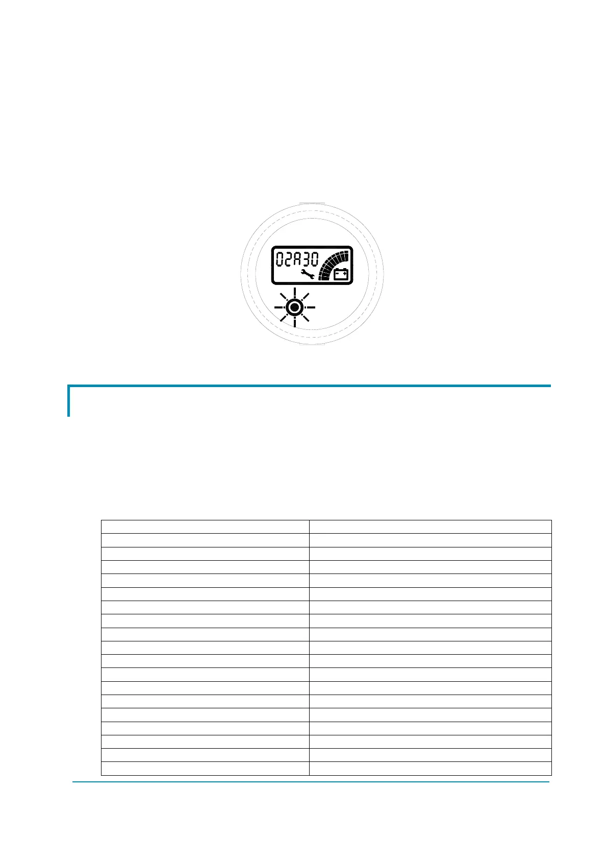
When an Alarm is generated, the Red LED blinks to attract the attention of the
operator. The symbol of Monkey Wrench also appears. The string shown on the
display is XXAYY, where XX and AYY represent respectively the alarmed node
and the alarm code. The alarm code meaning must be present in the controller
user manual.
4.1 Decoding of the alarms displayed on the MDI-CAN
Using the indication given by the MDI-CAN and after reference to the following
table, the operator can solve the problem, if the failure is not serious. It will also
be necessary to refer to the paragraph describeg the Alarms in the Manual of the
relevant controller.
If the Alarm information suggests or indicates a serious problem, the operator will
be able to give useful information to the Service Centre, thereby reducing down
time with relative costs savings.
A00 NONE
A01 CHOPPER RUNNING
A02 NO COMMUNICATION
A03 UNKNOWN CHOPPER
A04 CONSOLE EEPROM
A05 SERIAL ERROR 2
A06 SERIAL ERROR 1
A07 CHOPPER NOT CONFIG
A08 WATCHDOG
A09 FIELD FF FAILURE
A10 EEPROM DATA KO
A11 EEPROM PAR KO
A12 EEPROM CONF KO
A13 EEPROM KO
A14 EEPROM OFFLINE
A15 LOGIC FAILURE 5
A16 LOGIC FAILURE 4
A17 LOGIC FAILURE 3
A18 LOGIC FAILURE 2
 Loading...