Page - 30/50 AFGZP0BA – SMART CONSOLE - User Manual
4.2 CNX Connector
CNX is the main connector of the Smart Console.
The layout is a female DA-15 connector and it belongs to the D-subminature
family of connectors for computer and communication system.
4 DA-15 connector has been chosen because it is widely available on the market.
Even if Zapi is always available to design custom cables, the customer is
encouraged to create its own cables depending on its need.
U The connector has two threaded nuts which accept screws on the male
connector. It is strongly recommended to lock the screws in order to
improve electrical connection quality and to avoid undesired
disconnections.
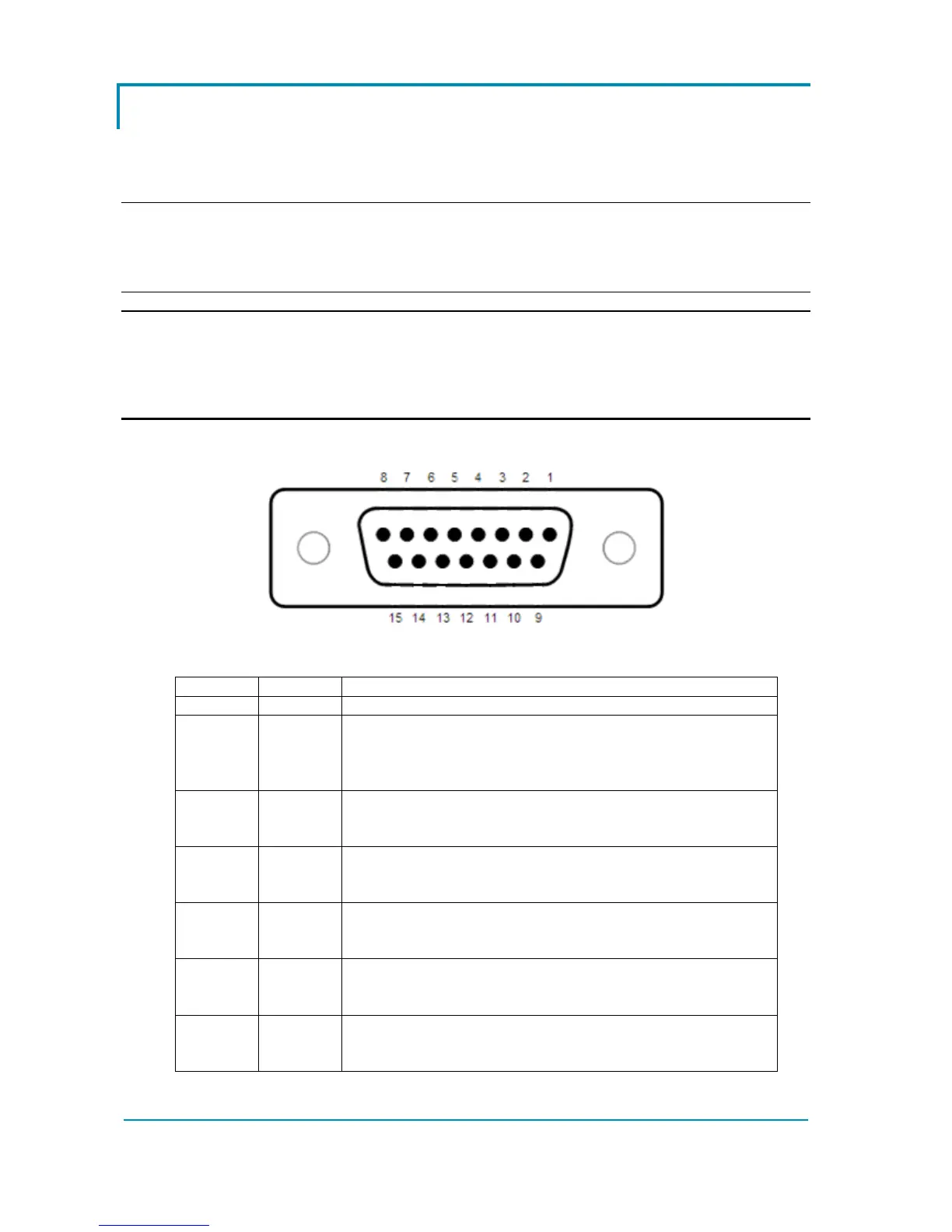
4.2.1 Layout
4.2.2 Pin description
PIN SIGNAL DESCRIPTION
CNX1 GND This is the ground of the console. Ground shall always
be connected to the ground of the
controller/application.
CNX2 PRX Positive of serial reception. It is a signal used in serial
communication only.
CNX3 NRX Negative of serial reception. It is a signal used in serial
communication only.
CNX4 NTX Positive of serial transmission. It is a signal used in serial
communication only.
CNX5 PTX Negative of serial transmission. It is a signal used in serial
communication only.
CNX6 CANL Signal of CANBUS interface. By default no 120Ω
resistance is placed between CNX6 and CNX7.
 Loading...


