AFGZP0BA - SMART CONSOLE - User Manual Page - 31/50
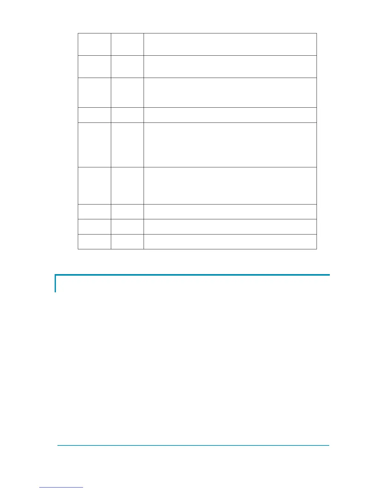
CNX7 CANH Signal of CANBUS interface. By default no 120Ω
resistance is placed between CNX6 and CNX7.
CNX8 +BATT This is the supply voltage when the console is used for
external supply. See 2.2.1 for electrical rating of this pin.
CNX9 BOOT If turned on with a short between this pin and ground, the
console will enter in boot mode. While in boot mode the
console firmware can be updated. In normal operation
this pin shall be left open.
CNX10 GND Same as CNX1
CNX11 +12V This is the input of the 12V coming from a controller
connected via serial cable. It is not a supply line. However,
if this signal is not fed, serial communication will be
impossible. Moreover this pin is used to detect the
presence of the serial cable.
CNX12 CANT
The 120Ω termination resistance is not needed
normally and it is not placed between CNX6 and CNX7.
If it is necessary to introduce it, make a short circuit
between this pin and CNX7.
CNX13 GND Same as CNX1
CNX14 NC Do not connect. For future use.
CNX15 NC Do not connect. For future use.
4.3 Cables
4.3.1 Serial cable
The Smart Console is shipped with a cable for connecting all Zapi products which
have the serial line
The connector at the controller-side is the same Molex SPOX type as the old
Console Ultra.
Moreover communication signals and protocol are the same as the old console.
 Loading...


