Maintenance & Technical Specifications 3 - 9
Digital Scanner Signal Descriptions
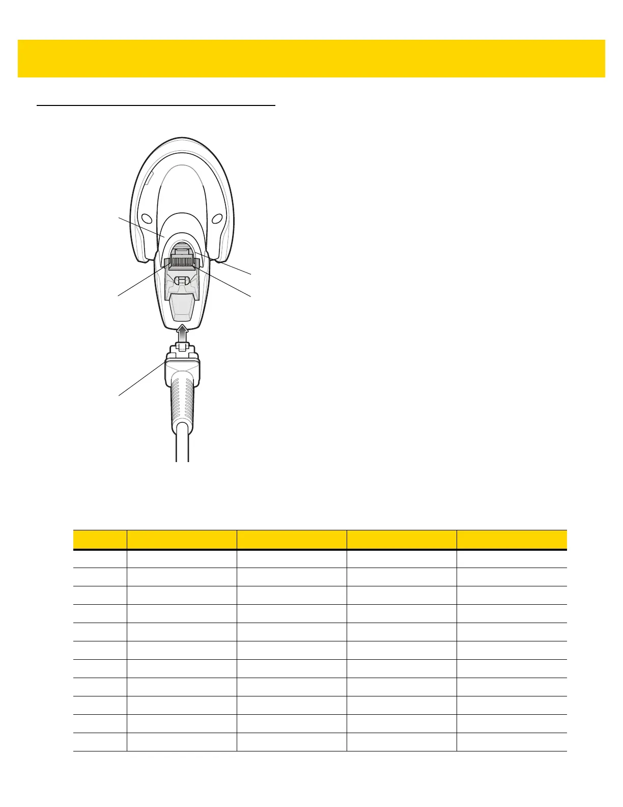
Figure 3-1 Digital Scanner Cable Pinouts
The signal descriptions in Table 3-3 apply to the connectors on the DS2208 digital scanner and are for reference
only.
Cable interface port
Interface cable
modular connector
Bottom of
scanner
PIN 1
PIN 10
Table 3-3 DS2208 Digital Scanner Signal Pin-outs
Pin USB RS-232 Keyboard Wedge IBM
1 Short to Pin 6 Reserved 1M Resistor to Pin 8 2M Resistor to Pin 8
2 Power Power Power Power
3 Ground Ground Ground Ground
4 Reserved TXD KBD_CLK IBM_TXD
5 D + RXD TERM_DATA IBM_RXD
6 Short to Pin 1 RTS KBD_DATA IBM_DIR
7 D - CTS TERM_CLK Reserved
8 Reserved Reserved 1M Resistor to Pin 1 2M Resistor to Pin 1
9 Reserved Reserved Reserved Reserved
10 Reserved Reserved Reserved Reserved
SHELL Shield Shield Shield Shield
 Loading...