9
0HDVXUHIURPUDQJHWRSWRKRRGERWWRPDQGPDUNOLQH$
´PLQLPXPIURPUDQJHWRS
3OXPDQGPDUNFHQWHUOLQH
0DUNPRXQWLQJKHLJKWOLQH%´IURPOLQH$
0DUNPRXQWLQJVSUHDGIURP&/RQOLQH%´
)DVWHQ[VFUHZVLQWRVWXGVRQOLQH%'RQRWIDVWHQ
screws all the way. Note: wood blocking may need to
be added behind the drywall if no studs are present.
Wall anchors may also be used but check local codes
for compliance. Failure to use suitable wall anchors
and screws to hold the weight of the hood could result
in personal injury or damage to cooking surface or
counter.
,QVWDOO´URXQGGXFWFROODUZLWKEDFNGUDIWGDPSHUWRWRSRI
KRRGE\[VFUHZV
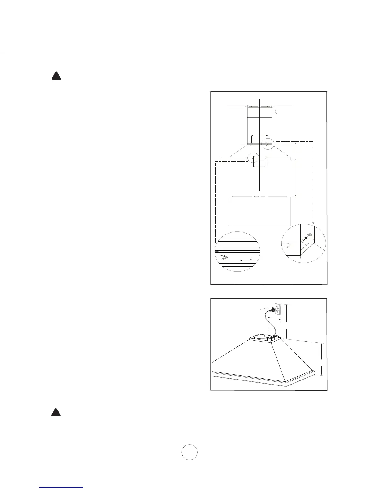
+DQJKRRGRQWRVFUHZVDQGKDQGWLJKWHQ),*$8VH
the last 4 x 38 screws to further secure the hood to the wall
IURPLQVLGHWKHKRRG),*$
&HQWHUDQGDWWDFKGXFWFRYHUEUDFNHWWRZDOOEHORZFHLOLQJ
RUVRႈWXVLQJ[VFUHZV
9. Position electrical outlet within the space covered by the
telescopic duct covers and where it will not interfere with
WKHURXQGGXFW),*%
,QVWDOOGXFWZRUNDQGGXFWWDSH
3RZHUXSKRRGDQGFKHFNIRUOHDNVDURXQGGXFWWDSH
12. Place telescopic duct covers onto hood and extend inner
WRSGXFWFRYHUXSZDUGVDQGVHFXUHWRGXFWFRYHUEUDFNHW
XVLQJ[VFUHZV
A
C
B
C/L
12-1/8"
1-3/8"
14-15/16"
13"
C/L
24" min
2
1
Duct Cover Bracket
CAUTION: At least two installers are
required due to the weight and size of the
hood.
!
WARNING: Electrical wiring must be done by a qualified person(s) in
accordance with all applicable codes and standards. This range hood must be
properly grounded. Turn off electrical power at service entrance before wiring.
!
Installation – Mounting the Hood
FIG. A
24”
MAX.
HOOD
CENTERLINE
4¼”
MAX.
12”
FIG. B
 Loading...