10 © 2009 ZTE Corporation. All rights reserved. ZTE Confidential Proprietary
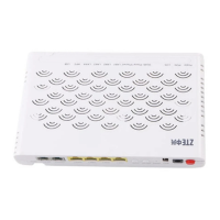
Figure 8 ZXR10 2600 Hardware Architecture with Fixed Ports
SDRAM
FLASH
CPU
CONSOLE
Switching network
controller
PHY
Integrated PHY
The system hardware consists of the following parts:
• 10/100M PHY: used for data coding. 1-port chip is used on the 10/100M PHY.
• Switching network controller: Adopts the high performance ASIC chip technology to
provide the wire speed layer 2 forwarding of data packets.
• CPU: A cost-effective CPU to control the whole system.
As shown in the figures above, switching system of the ZXR10 series adopts the bus
structure. The port capacity of 2609 and 2609-FU is 1.8 G and the bus bandwidth is
6.4G.
4.3 System Software
4.3.1 Overview
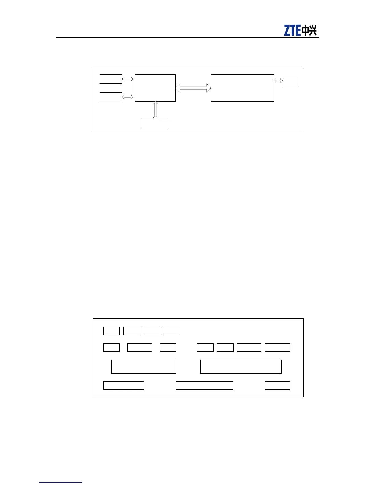
Ошибка! Источник ссылки не найден. shows the software architecture of the
ZXR10 2600 series switches.
Figure 9 Software Architecture
BSP
Embedded OSSwitch driving
Protocol interface
encapsulation layer
Configurationmanage
ment interface layer
VLAN
SNMP
TFTP ConsoleTelnet802 . 1 x IGMP
GVRP STP MSTP RSTP
As shown in Figure 9, the software architecture adopts the bottom-up hierarchical design.
By operation, the software architecture is divided into a service plane and a
management plane. The service plane forwards service data, including necessary
 Loading...