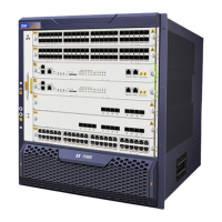
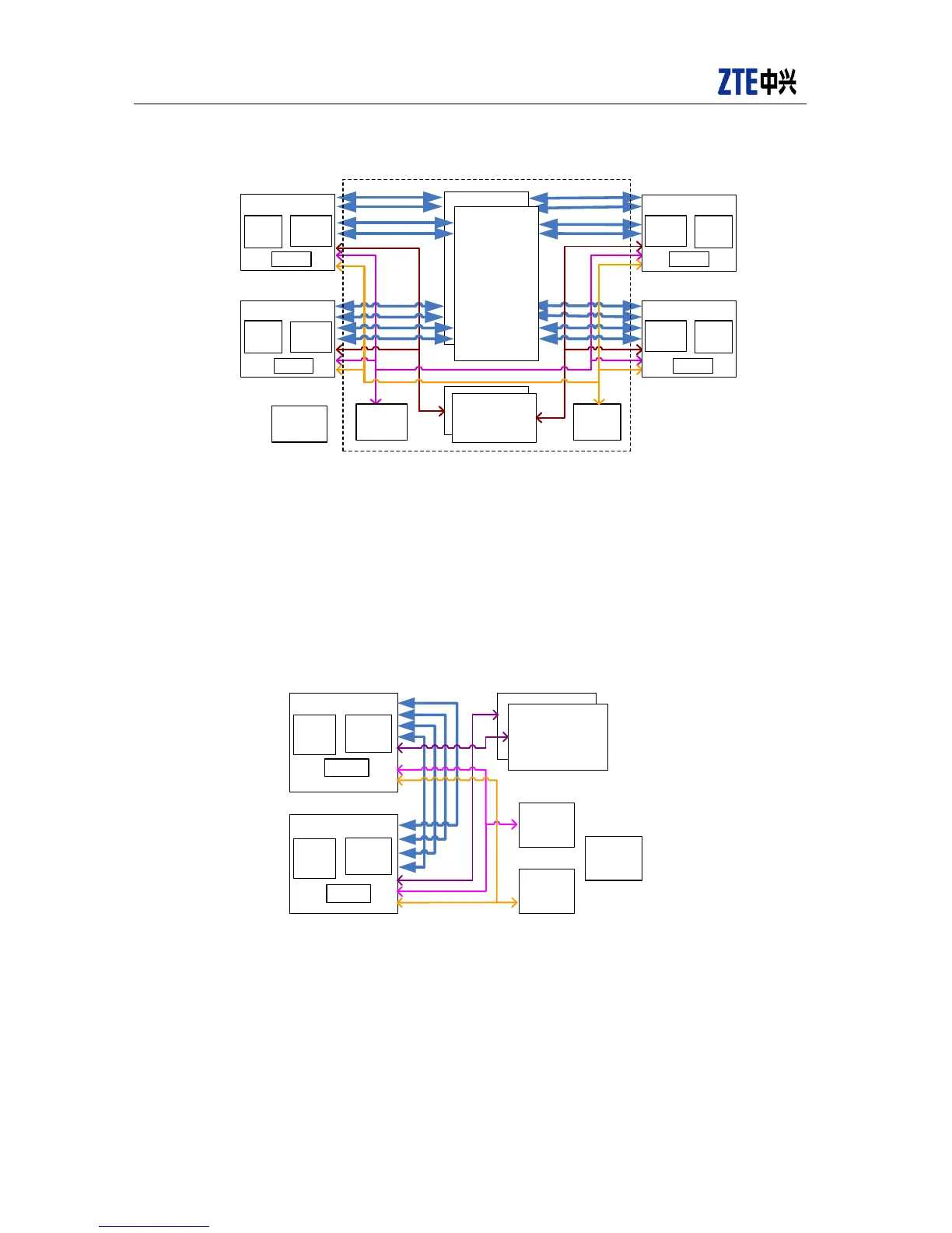
Figure 4-11 ZXR10 8905E/8908E/8912Esystem hardware diagram
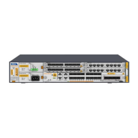
The switch structure for ZXR10 8902E is different in switching plane. When 8902E switch
conducts two-layer hardware switching, layer 1 switching is implemented between ports
of line cards. Layer 2 switching is implemented between two line cards by the high-speed
Serdes bus directly connected to line cards. The system diagram is shown in Figure 4-12.
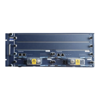
Figure 4-12 ZXR10 8902E system hardware diagram
 Loading...